Category Archives: Arduino

Blast from the past: Arduino Origins

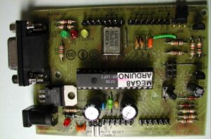
Someone in the Arduino forums mentioned they were having troubles with their Single Sided Arduino board that they built on their own.   It reminded me that I wanted to make one for myself.  I needed an extra Arduino I could use for RS485 testing and a NON-USB one was preferred.

What a great afternoon project this is.  I took the toner transfer PNG file and printed it out so I could use the laminator to do a toner transfer. Once it was etched I could really see the benefit of having a silkscreen on the topside… the trouble is, I’ve never done a board with imagerey on top.   I first tried using a heat transfer…  just like I did with the copper side but I had no luck.  After 10 times through the laminator I still had no luck bonding the toner with the fiberglass side.  (I sort of figured that would happen…)

I remembered that I had some 8 1/2 by 11 blank decal sheet on hand and thought maybe I could float the silk screen  side decal onto the surface.   OK… having never done this  before I’m going to now admit I was a bit overconfident,  this is really not easy.

Eventually I got it applied.  I lost a few bits here and there, but the important parts didn’t tear off.  I wanted to coat the decal with FUTURE floor wax but I could not locate the bottle I had for this purpose.  It would be a good idea though.

Anyway… here are the results.  Powered it up and loaded a sketch…  Yippie.

Arduino IDE on Ubuntu – easy way

Here is the simplest way to get the latest Arduino IDE installed on a freshly installed  Linux Ubuntu distribution.  The version of Arduino that is in the default repository is now a few years old, and in fact, the version you will get is officially “…no longer supported by the development team.”

But, there is an upside to this.  By performing the following command you get a complete guided installation that will install all the compiler dependencies and do nice things such as making your account part of the dialout group, which is needed to access the serial port.


sudo apt-get install arduino

So, with this accomplished lets download the latest version from
Arduino Download Page and make sure you choose the linux version that matches your system (32 bit or 64 bit).

Version

NOTE: The latest version is subject to change, so replace references to “1.6.8” with what ever the current downloadable version is.

The installation kit will normally end up in your “Downloads folder” so lets open a terminal window and go there to unpack it.


$ cd Downloads/
$ ls
arduino-1.6.8-linux64.tar.xz
$ tar -xvf arduino-1.6.8-linux64.tar.xz

This will place the files in a new folder named: arduino-1.6.8

Now, we can place it anywhere, but a nice place to put it is in the /opt top level folder. This can be accomplished with the following step:


sudo mv arduino-1.6.8 /opt

Now, move your /opt folder by typing:


cd /opt/arduino-1.6.8

and then issuing the following command to make this installation of arduino “go live”


chmod +x install.sh
./install.sh

You should now have an Arduino icon on your desktop that will open the latest “supported” version of the IDE.

An approach to writing Arduino code

Code Review

Let’s do an example of code development.

Let’s say that we are reading analog values for ranges and want to make decisions based on ranges to set ranges of values. We start with the following snippet. The `if` statements quickly become wordy and program flow maybe starts to become unclear.  So lets look at some ways to unravel this with a subroutine.


reading = analogRead(1);

int state = 0;

if (reading > 0 && reading < 500){ 
state = 1; 
} 

if( reading > 499 && reading < 700) { 
state = 2; 
} 

if ( reading > 699  && reading < 1025) {
 state = 3;
}

You could just write a small procedure  to simplify this comparison test series…


bool inRange(int x, int y, int z){

 if (x => y && x <= z) {
      return true;
     } else {
      return false;
     }
}

and then call it with much easier to read process requests… like the following code.


//file inrange.ino

// State 1: Connect analog pin to gnd
// State 2: Connect analog pin to 3.3V
// State 3: connect analog pin to 5V

int reading;
int state = 0;

void setup() {
  // put your setup code here, to run once:
 Serial.begin(9600);
}

void loop() {
  // put your main code here, to run repeatedly:
reading =  analogRead(1);

  if(inRange(reading,0,500))
     state = 1;
  
    if(inRange(reading,500,700))
       state = 2;
    
      if(inRange(reading,700,1024))
         state = 3;
      
    Serial.print("Reading ");
    Serial.println(reading);
    Serial.print("state: ");
    Serial.println(state);
    delay(1000);
}

//-------------------------------------------------
// Notice the use of non-informative variable names
// we should fix this.

int inRange(int x, int y, int z){
   bool val;
   if (x >= y && x <= z) {
      val =  true;
    } else {
      val = false;
    }

    return(val);
  }


See? You really get some better logic flow this way.

New lets go a step further… using space saving `const` or constants.


// File: inrange1.ino

// State 1: Connect analog pin to gnd
// State 2: Connect analog pin to 3.3V
// State 3: connect analog pin to 5V

//=====[ CONSTANTS ]============================================================
//Still a bit wordy here...
const int RED = 0;
const int GREEN = 1;
const int BLUE = 2;

//=====[ PINS ]=================================================================
int anPin = 1;


//=====[ VARIABLES ]============================================================
int reading;
int state = 0;


void setup() {
  Serial.begin(9600);
  // Wait for USB on Leonardo and similar devices
  while (!Serial) {
  }

}

void loop() {
  reading =  analogRead(anPin);
  
  // debugging code...
  Serial.print("Reading ");
  Serial.println(reading);


  if (inRange(reading, 0, 499)) 
    state = RED; 
    
  if (inRange(reading, 500, 699)) 
    state = GREEN;
  
  if (inRange(reading, 700, 1024)) 
    state = BLUE;
    
  ColorState();

  delay(1000);
}

//==============================================================================

int inRange(int passVal, int minVal, int maxVal) {

  if (passVal >= minVal && passVal <= maxVal) {
    return true;
  } else {
    return false;
  }
}
//==============================================================================

void ColorState() {
  Serial.print("State: ");

  switch (state) {
    case RED:
      Serial.println("Red");
      break;
    case GREEN:
      Serial.println("Green");
      break;
    case BLUE:
      Serial.println("Blue");
      break;
    default:
      break;

  }
}

Now we start to see how to break out sections of code into useful re-usable subroutines. So lets take this one step further and refine it into a final version using the `enum` command. Notice how the code becomes even a tiny bit simpler.


// File: inrange3.ino

// State 1: Connect analog pin to gnd
// State 2: Connect analog pin to 3.3V
// State 3: connect analog pin to 5V


enum States {
  RED,
  GREEN,
  BLUE
};

States state = RED;  // use the enumeration and initialize to RED

//=====[ PINS ]=================================================================
int anPin = 1;


//=====[ VARIABLES ]============================================================
int reading;

void setup() {
  Serial.begin(9600);
  // Wait for USB on Leonardo and similar devices
  while (!Serial) {
  }

}

void loop() {
  reading =  analogRead(anPin);

  if (inRange(reading, 0, 499))
    state = RED;

  if (inRange(reading, 500, 699))
    state = GREEN;

  if (inRange(reading, 700, 1024))
    state = BLUE;

  ColorState(state);

  delay(1000);
}

//==============================================================================

int inRange(int passVal, int minVal, int maxVal) {

  if (passVal >= minVal && passVal <= maxVal) {
    return true;
  } else {
    return false;
  }
}

//==============================================================================

void ColorState(int range) {
  Serial.print("Condition: ");

  switch (range) {
    case RED:
      Serial.println(" Red");
      break;
    case GREEN:
      Serial.println(" Green");
      break;
    case BLUE:
      Serial.println(" Blue");
      break;
    default:
      break;

  }
}


So while this is not the best code, it definitely accomplishes the simplification goal in the main process loop.

Food for thought.

Arduino rant

Programming Framework

This post is about coding as much for yourself as for others. While it’s really easy to write pages of code with only a few comments, in the long run, writing well structured and clearly legible code helps a lot when you return to it months later and are forced to ask yourself “What was I thinking?”

Programmers Lament: ‘I think I wrote this section of code late at night after I had a few beers with friends. I think I need to go out and have a few beers to understand why I wrote it like this.’

I try to write all my code as if I was about to post it to public blog and that the reader will have only rudimentary knowledge of what my goal is. This means that I will need to explain myself clearly. This will impact the kind of comments I write and will remind me that resorting to cute code tricks and obfuscation (even accidental) is a bad idea.

I will admit that I am not a professional programmer, but I play one on IRC. Joking aside, I am not even a trained programmer unless you count reading books on programming. My advice here comes from concepts I have learned through years of reading other peoples code. I have found that what I call the “good” code is written by someone who is well organized writes decent comments and is reasonably methodical in how they break down a problem. Some of my own ideas start as inspiration from these organized and creative programmers whose shoulders I stand on. I will show you a programming template technique I learned from Jon McPhalen. See what I did there? Programming rule #1 should be, “Always include attribution and give appropriate credit for your borrowed ideas”.

While there are some decent books on programming style, it’s not the main focus here. This is about remembering that you could have a future audience that reads your code, so writing efficiently, being consistent and adopting good conventions is paramount.

Using a template for organized code

The Arduino environment already enforces a certain method of coding on us. It requires us to write using the core C++ language and that we employ two sections of functionality in our code. So the base minimum code is the well understood:

void Setup() {

} 

void Loop() {

}

While it is nice that the Arduino developers have saved us a lot of trouble but making “getting started” so easy, it doesn’t much help when you come back later to revise your code later and are clueless because you thought, “I’ll make it pretty later” and you never do. I have adopted a starting point for code that includes some more information than just the bare minimum required. The goal here is to start with a template that is nicely sectioned out so you have a road map for moving forward.


Here is an example of a template as a starting point:

//==============================================================================
// TTTTT EEEEE M   M PPPP  L      AAA  TTTTT EEEEE        III  N   N OOOOO 
//   T   E     MM MM P   P L     A   A   T   E             I   NN  N O   O 
//   T   EEEE  M M M PPPP  L     AAAAA   T   EEEE          I   N N N O   O 
//   T   E     M M M P     L     A   A   T   E      ..     I   N  NN O   O 
//   T   EEEEE M   M P     LLLLL A   A   T   EEEEE  ..    III  N   N OOOOO 
//==============================================================================
//==============================================================================
// Program: template.ino
// Author: Pete Willard
// Version: 1.0
// Target: Uno
// Date: 2015/04/02
// Time: 06:41:02
// Notes:
//
// ----------------------------------------------------------------------------
// 'THE BEER-WARE LICENSE':
// petewillard@gmail.com: As long As you retain this notice you
// can do whatever you want With this stuff. If we meet some day, And you think
// this stuff is worth it, you can buy me a beer in return. Pete Willard
// ----------------------------------------------------------------------------
//
// Reference:
//==============================================================================

//=====[ INCLUDE ]==============================================================

//=====[ CONSTANTS ]============================================================
#define DEBUG 1 // 0 = debugging disabled, 1 = enabled

//=====[ PINS ]=================================================================
int onboardLed = 13;

//=====[ SETUP ]================================================================
// Runs only one time at startup
void Setup() {
pinMode(onboardLed,OUTPUT);

}

//=====[ MAIN PROCESS LOOP ]====================================================
void Loop() {

}

//=====[ SUBROUTINES ]==========================================================
void printBreak() {
Serial.println("=============================");
}


I actually went so far as to write a small program that uses a fill in form to create this template format on demand. It even creates that retro-style banner with the file name spelled out on top.

A quick review shows that the template has defined a sample constant that you can use while debugging code. Changing this constant between 0 and 1 will enable you to write some conditional code that will print or stop printing debugging data with just 1 edit.

It also contains an example of using meaningful names. Using the variable assignment such as ‘onboardLed’ for pin 13 helps to make the code more readable.

Variable names don’t have to be short and are much better when multiple words are compounded into a meaningful descriptive names. For enhanced readability, try to avoid using using ALLCAPS and avoid variables with leading underscores. Try to adopt the much more accepted “camelBack” notation. This notation starts with lowercase and is the practice of writing compound words or phrases such that each following word or abbreviation begins with a capital letter*. Inserting underscores inside variable names makes the camelBack method redundant so just pick either one and stick with it.

* The case where the leading letter is lowercase but all subsequent words are capitalized is also called the Microsoft style.

Modular thinking

To me, when it comes to reading other peoples code, there is nothing more disturbing than reading page full of if conditional statements that include redundancies and a clear sign of poor planning. If I need to keep track of more than a few conditions while reading code I find that the logic of what “was intended” to be easily lost.

My approach to solving this has always been to create function blocks of code and keep the main section, in our case the Loop(), as clear and readable as possible. In C, this is called creating a “function” and it is sometimes referred to as a procedure or subroutine. I personally use all three terms interchangeably.

In most cases, you will write a procedure that accepts an argument and returns a result but this is not a requirement. For example, you can have a subroutine that just performs a task that makes the rest of your code look cleaner. Like this:

void printBreak() {
  Serial.println("=============================");
} 

So in your main code, all you need to type is:

printBreak();

In one of my programs, I have a Loop() section that basically contains 3 steps:

sampleSensors();	// collect all external sensor variable data into a “struct” variable</span>
printResults();	// send the results in 1 CSV formatted line</span>
cycleCheck();		// is it time to get updates from sensors?</span>

The functionality of the loop section remains readable and it is not bogged down with actual logic decisions. The logic and action steps are reserved for the procedures themselves and the procedures call other procedures to keep things organized. Breaking up tasks will actually help make your procedures more useful and in a lot of cases… re-usable.
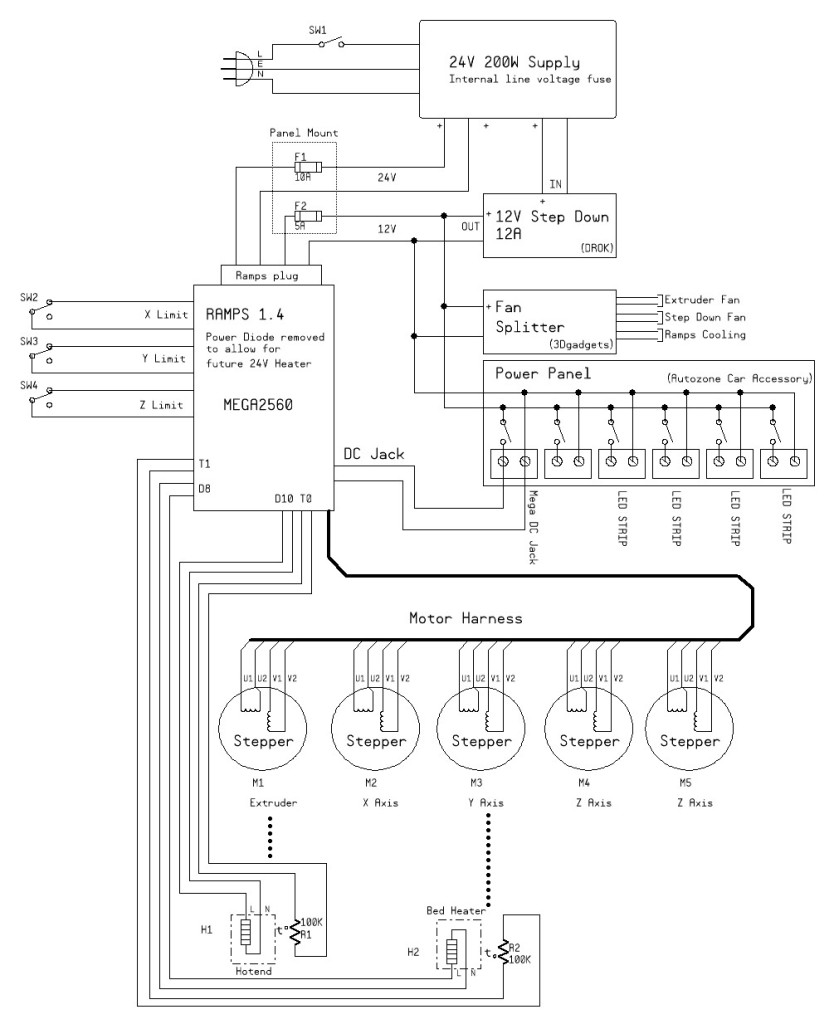
I finally got around to documenting how I wired my MendelMax 3D printer

Mendelmax wiring

Mendelmax wiring

I recently added a 24V Kapton heatbed and new Y rail system to replace the finicky dual rod system. The upgrade required me to remove the existing 12V power supply and replace it with a 24V 200W supply. Since only the new heater in the bed requires the 12V I also installed an adjustable Stepdown DC/DC regulator (A 12A unit for sale on Amazon for about #$12 under the name DROK). The unit does get slightly warn during use, so I added a small fan for the smaller regulator that supplies 12V for all the motors, the controller boards and the fans.

The power for the Arduino mega is controlled via a switch from a 12V distribution panel I purchased at Autozone designed to allow power control for up to 6 unique devices. So the unit can still run standalone if needed. I removed the Diode on the Ramps 1.4 board that supplies power to the Arduino since there are those times when you just want to kill power to the arduino board.

The on board Polyfuses were removed and replaced by a piece of hookup wire.  The fuses for the power source are now panel mounted using standard 3AG fuse holders.

Note: My USB cable that comes from the PC already has a switched power option.


On a side note: Working with Brian at Ultibots regarding my Y axis upgrade was a superbly positive experience.  Ultibots is now my first choice for parts. 

So… I ordered a Spark Core…

… and these things are really neat.

Ok, so what is a Spark Core?   Wait…  lets start with the fact that this was a Kickstarter project that succeeded and is now a full fledged product that sadly I did not know about until afterwards.  I’d have been there supporting this Kickstarter if I had known about it. I tried to support a different but *very* similar Kickstarter project (well, not tried, I did support it) and have yet to see the product that is now many many months late. Now that I have the Spark core, and I like it, I’m pretty sure I won’t care when the Flutter *finally* arrives.

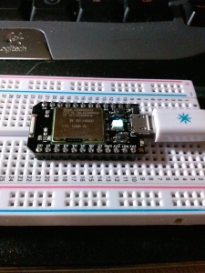
spark core image

spark core


So, back to what a Spark Core is.  It is a small device, roughly the size of an oversize collector edition US postage stamp.  It’s designed to fit into a Solder-less breadboard for easy project development and comes in 2 flavors… one with an on-board “chip” antenna and one with a small antenna jack that allows you to install your own wifi antenna… I grabbed an antenna out of my pile of broken wifi routers.  I wasn’t sure it would work… but seems to work just fine and uses the same RF jack (imagine that?).

For more information on what a Spark Core is, go here: Spark Core Getting Started

So what am I doing with it? Well, I’m learning what it can do first… and that’s a tiny bit tricky. The documentation is written more geek than noob friendly and while I have no issue with the documentation in general, it does seem to have some gaps here and there. I suppose with time this will all get better.

For example; they did make it seem like it would do some automagic things to get it quickly “registered” in the cloud and that my phone app could talk to it right away. No such luck. My Phone app never found the device and the status LED said I was happily connected. I needed to go through a rather manual process of attaching to the device in a serial debug mode to capture my unique ID to claim my core manually. Again, it was supposed to just work… but a quick check says I’m not the only one this happened to. (ed. I did acquire an additional spark core and the second one installed and connected and was claimed without a hiccup)

With that initial stumble out of the way… I needed to see how Arduino compatible this is so I started writing some code. As long as I stick to true Arduino’s abstract language (and not hardware dependent short cuts like you might find in some existing libraries) all is well. This device does not have an AVR MCU at it’s heart. It uses an STM32 MCU which is a much more capable device coupled with a TI CC3300 wifi in-a-box chip to create a complete arduino-like wifi device in a seriously small package.

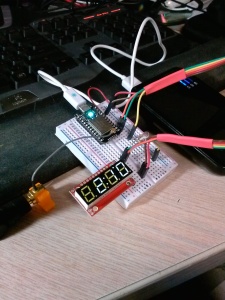
My first project on the device after playing with examples is a simple “always correct” LED clock using the SparkFun 4 digit seven segment serial LED. It works… and displays the correct time as soon as it boots up with no need for battery backup or an RTC chip. The part number COM-11629. This is a mildly depressing LED display due to the fact that it is running on 3.3 volts and has 1000 Ohm current limiting resistors on the LED’s. (Did I mention that the Spark Core is a 3.3V device? No? oops.)

Seriously… 1000 Ohms at 3.3 volts is not the ideal value of the current limiting resistors. It should be around 47 Ohms… not 1000 Ohms. The end result is you can only really see the display in the dark.

2014-12-05 14.10.37

Anyway… the code part works… It uses built in features like wire library and time library that are already in the API. Here, see for yourself*…


//==============================================================================
//  III  2222   CCCC  CCCC L     OOOOO  CCCC K   K
//   I       2 C     C     L     O   O C     K  K
//   I    222  C     C     L     O   O C     KK
//   I   2     C     C     L     O   O C     K K
//  III  22222  CCCC  CCCC LLLLL OOOOO  CCCC K   K
//==============================================================================

//==============================================================================
// Program:      I2Cclock
// Author:       Pete Willard
// Version:      1.0
// Target:       SparkCore
// Date:         2014/12/04
// Time:         08:14:45
// Notes:

// This program is free software: you can redistribute it and/or modify
// it under the terms of the GNU General Public License as published by
// the Free Software Foundation, either version 3 of the License, or
// (at your option) any later version.

// This program is distributed in the hope that it will be useful,
// but WITHOUT ANY WARRANTY; without even the implied warranty of
// MERCHANTABILITY or FITNESS FOR A PARTICULAR PURPOSE.  See the
// GNU General Public License for more details.

// You should have received a copy of the GNU General Public License
// along with this program.  If not, see <http://www.gnu.org/licenses/>.

//
// Reference:
//  Used rather sketchy Sparkfun serial LED display "datasheet"
//  Part #  COM-11629 - Note: it's a rather dim display.
//==============================================================================
 # define bitSet(value, bit)((value) |= (1UL << (bit)))
 # define bitClear(value, bit)((value) &= ~(1UL << (bit)))

//=====[ CONSTANTS ]============================================================
// # define DEBUG 0 // 0 = debugging disabled, 1 = enabled
//This is the default address of the OpenSegment with both solder jumpers open
 # define DISPLAY_ADDRESS1 0x71

// definitions from sparkfun for bitwise led controls (decimal/colon/dot)
 # define COLON 4
 # define DOT 5

// Time Sync and Time Zone settings
const int syncInterval = 60 * 60 * 8; //sync every  4 hours

static signed char const DEFAULT_TIME_ZONE = -4;

//=====[ VARIABLES ]============================================================
long millisTimer;
int lastSync = 0;
boolean colonOn = false;
boolean ampm = true;
char bits; // used to track binary values for bitwise

//=====[ SETUP ]================================================================
void setup() {


	Spark.connect();
	 while(Spark.connected() == false) {
	     delay(100);
	 } while(Time.year() == 1970)
	  {
	     Spark.syncTime();
	     Spark.process();
	     delay(100);
	  }
	 Spark.disconnect();
	 while (Spark.connected() == true) {
	     delay(100);
	     Time.zone(DEFAULT_TIME_ZONE);
	 }
	 
	Wire.begin(); // join i2c bus as master
	Wire.beginTransmission(DISPLAY_ADDRESS1); // transmit to slave device #4
	Wire.write('v');
	Wire.write(0x7A); // Brightness control command
	Wire.write(100); // Set brightness level: 0% to 100%
	Wire.endTransmission(); // stop transmitting

}

//=====[ MAIN PROCESS LOOP ]====================================================
void loop() {
	ampm = Time.isAM();
	showTime();
	delay(1000);
	adjustTime();
}

//==============================================================================
void adjustTime() {
	if (lastSync + syncInterval < Time.now()) {
		Spark.syncTime();
		lastSync = Time.now();
	}
}

//==============================================================================


//==============================================================================
//  Must be called after a "begin.transmission()" command.
//==============================================================================
void colonFlash() {
	//Blink the colon every other second

	if (colonOn == true) {
		colonOn = false;
		bitClear(bits, COLON);

	} else {
		colonOn = true;
		bitSet(bits, COLON);

	}
	Wire.write(0x77); // control command
	Wire.write(bits); // Turns on colon
}

//==============================================================================
//  Must be called after a "begin.transmission()" command.
//==============================================================================
void setPM() {
	if (ampm == true) {
		bitClear(bits, DOT);
	} else {
		bitSet(bits, DOT);
	}

	Wire.write(0x77); // control command
	Wire.write(bits); // Turns on colon

}

//==============================================================================
void showTime() {
	char out[] = {
		0,
		0,
		0,
		0
	}; // place holder for time array

	char hour = Time.hourFormat12();
	char min = Time.minute();

	sprintf(out, "%2d%02d", hour, min); // format current time into char array
	Wire.beginTransmission(DISPLAY_ADDRESS1); // begin I2C transmit to device

	setPM();
	colonFlash();

	for (byte x = 0; x < 4; x++)
		Wire.write(out[x]); //Send a character from the array out over I2C
	Wire.endTransmission(); //Stop I2C transmission

}


So, how does Serial.readBytesUntil() work?

I’ve been toying with the idea of setting the clock on my Arduino RTC (a DS3234 dead-on real time clock) because even though it still keeps good time, it’s still impacted by daylight savings time changes and because setting the time using a boot-loader based upload can be such a hit or miss sort of thing.

So, to accomplish this in as close to real-time as possible, I started thinking about how I could send commands to the arduino from Python code on my Raspberry Pi. I opted for a COMMAND,DATA structure to simplify parsing.

The goal is to keep it simple and to use a part of the serial library that I have not used yet: “Serial.readBytesUntil()” while avoiding the requirement to include “string.h” in my code. Why? Because I need this to be part of a larger program that already stretches the limits of available RAM on my UNO. The upside of using “readBytesUntil” is that you don’t have to keep checking the input buffer and assemble an array of char… the downside of using “readBytesUntil” is that it has a default timeout of 1 second. So how useful this is in the end remains to be fully tested.

Right now, there is no bounds checking… so if the command text is larger than 10 chars and data is larger than 15, you get “unpredictable” results.

Arduino Code:


//==============================================================================
// Program:      SerialParse.ino
// Author:       Pete Willard
// Version:      1.0
// Target:       UNO R3, IDE 1.03 
// Date:         2013/04/08
// Time:         09:47:54
// Notes:        
//               Uses Serial I/O
// Reference:    
//==============================================================================
 
//=====[ INCLUDE ]==============================================================
//#include <stdlib.h>
 
 
//=====[ CONSTANTS ]============================================================
#define   DEBUG   1   // 0 = debugging disabled, 1 = enabled
const int bSize = 20; 
 
//=====[ PINS ]=================================================================
int Led = 13;
 
//=====[ VARIABLES ]============================================================
 
    char Buffer[bSize];  // Serial buffer
        char Command[10];    // Arbitrary Value for command size
        char Data[15];       // ditto for data size
        int ByteCount;
 
//=====[ SUBROUTINES ]==========================================================
 
void SerialParser(void) {
//
//  One command per line.  Eventually, Data may have multiple 
//   fields separated by ":"
//  Command Format: "up to 5 Letter command, up to 10 letter data<\n>"
//                  No checking.
//
//  count will  be below Zero on a timeout.
//  read up to X chars or until EOT - in this case "\n" 
 ByteCount = -1;
 ByteCount =  Serial.readBytesUntil('\n',Buffer,bSize);  
 
   if (ByteCount  > 0) {
        strcpy(Command,strtok(Buffer,","));
                  
        strcpy(Data,strtok(NULL,","));             
   }
   memset(Buffer, 0, sizeof(Buffer));   // Clear contents of Buffer
   Serial.flush();
}
 
 
//=====[ SETUP ]================================================================
void setup() {
    Serial.begin(9600);
    pinMode(Led,OUTPUT);
    if (DEBUG) {
        Serial.println("Debugging Enabled");
    }
     
}
//==============================================================================
 
//=====[ LOOP ]=================================================================
void loop() {
 
    SerialParser();
         if (ByteCount  > 0) {
          Serial.print("Command     : ");
          Serial.println(Command);
          Serial.print("Data        : ");
          Serial.println(Data);
         } 
       
}

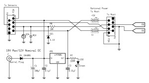
1-wire Power Injector

One way that I get reliable 1-wire communication is to use a power injector. This means that the along with the 1-wire signals, I inject a supply voltage into additional cable pairs.  Since  the most readily available commodity cable currently is 8 conductor Cat-5 cable, chances are that you also use this cable for 1-wire cabling and have spare wires going unused. Dallas called the 1-wire bus a MicroLAN, so I will continue to use their terminology here.

For short runs, where the total length of the MicroLAN is < 30 meters and the network only has maybe 6 to 10 slave devices on it, cable selection for use on the MicroLAN is reasonably simple, as even flat modular phone cable can work with a small numbers of 1-Wire slave devices. However, the longer the MicroLAN, the more important cable properties and therefore cable selection becomes more critical.  However, since I’m dealing with 30M or less, I’ll focus on that here and leave the research for  better cable techniques for when I run into a problem.

One of the remaining issues with using 1-wire driven from an Arduino pin directly is the fact that it is also providing power to all of the devices on the the 1-wire LAN when in parasitic mode.   While 1 or 2 devices are of little concern, I started to worry about building a reliable 24/7 full time  MicroLan configuration that would report weather data from 8 or so sensors, most of which were located at the garden bed outdoors.  It became clear that some of my devices were really not performing as desired  when “parasitically”  powered when I finally put all the pieces together.

Experimentation showed me that the signal from the Arduino pin was just not up to that task of powering and communicating with all the devices without some random miscommunication here and there.  I would get values like 185F and not the 70F I was expecting from a 1-wire temperature sensor, for example.

My solution was reasonably simple.  I would create an external “middle-man” device that would insert power into the CAT-5 cable after leaving the Arduino board.  Its really just a dual supply from typical commodity wal-wart power source.  The unmodified 12VDC supply will be fed into the cable on a spare pair and treated as “unregulated” and a 5V regulator will be added to another spare pair and considered to be “regulated”.  All code will now be written to comply with the “non-parasitic” mode of 1-wire.

The Design:
1wire-power-injector

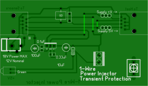
The PCB:
PI

LC Meter – Working…

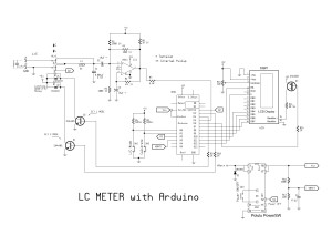
This is a variation of many many other LC meters already published. It owes much of it’s design to the AADE LC meter that relies on the oscillation of a standard Analog Comparator using a capacitor and a coil. This solution is an attempt to take Kerry Wong’s Arduino implementation and simplify it a bit and to make use of latching relay for mode selection.

Notes: Initially I used a 2% tolerance .001uF capacitor and a small 5% tolerance RFC 220uH coil. results were OK, but not real close to actual values even after some tweaks so I looked for an alternative in my junk box.

I found a 1800pF Mica capacitor with 1% tolerance and a 82uH radial choke coil (Basically, the kind used in higher current situations). I did some quick math and determined that frequency of oscillation would increase to somewhere between 414473 HZ and 419973 HZ with the former being the mathematical ideal. (which I modded to an even 420000 for simplicity.)

My changes (completed and planned) to the Kerry Wong’s solution includes:

1) Software controlled backlight – no switch – I just turn it on… that works for now
2) Implementation of Latching Relay to eliminate a DPDT manual switch
3) Using an 8×2 LCD for smaller footprint
4) Battery Voltage sensing. If battery is low, shut off the backlight.
5) Push-on/push off power control with timer based auto shutoff. (5 minutes)

Testing showed me that I really didn’t like using the KHM Library from Martin Nawrath. I mean, it basically worked and that is what Kerry Wong used… but, I found that it was impacting my mode switch and calibrate button sensing. And that was just not good now that I was using a latching relay instead of a DPDT switch for mode change.

In the end, I opted for the Frequency counting library from PJRC instead:

CODE

Sprint Layout File:
Sprint Layout (V6)

Schematic:
MyPCB-LC-Chematic

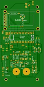
Layout (only 2 minor errors crept in during etching):
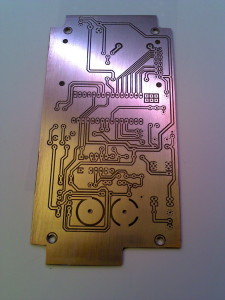
MyPCB-ASBuilt

Etched PCB (tinned and sealed with matte clear laquer AKA Dullcote):
2013-05-04_21-37-03_810_zps5de5a16b

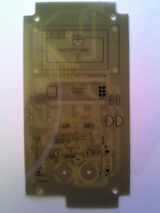
Silkscreen: Toner Transfer to TOP SIDE PCB, sealed with Future floor wax (clear acrylic)
2013-05-04_21-36-33_802_zps7ff47096

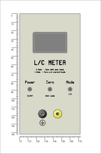
Front Panel:
panel2

PD2435 and Arduino using I2C Port Expander

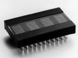
This information has been collecting dust on my hard drive.   Time to resurrect it…  Recently I have been working on a Temperature and  Humidity display and while working on it,  decided to use these RETRO parts I got from BGMICRO sometime around 2000. Even then, these parts were considered “pure unobtanium”.  I still had a few leftover displays, so out from the parts collection they come.

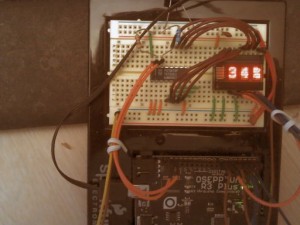
Now I had never taken the time to really get these displays working on an Arduino and what I really wanted was a test that would show off how much information you can really show using only 4 characters.

Since this project was to be inserted into an already working sketch, I made sure it was as modular as possible, sprinkled with subroutines that could be called from “who knows where” to get the job done.

I’ve tried to comment where it made sense and I have drawn up a quick schematic drawing to show just how its connected.  Since this part was designed for a CPU Bus Architecture of the 70’s and 80’s, it is annoying to see how demanding it is of the limited pin resources on the Arduino. The display assumes you provide data in a Parallel 8-bit format.  To relax this demand for pins, I employed a PCF8574 ( I2C port expander) that was harvested from some abandoned electronic board.  “YAY for recycling!”

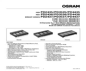
The parts I’m talking about are the PD243x displays from OSRAM.

So, what we have here is some sample code, for the Arduino, that allows you to send ASCII strings (including text scrolling) to these vintage displays.  Some of the information that helped me get beyond the datasheet was gathered from around the Internet (including blogs in New York, Japan and Korea)  Kudo’s to TechBlog in Korea for creating such a great resource.

display

Interesting side story: WAY BACK WHEN… BG Micro had horrible 3rd party photocopies of a facsimile for these parts. They were almost entirely unreadable.  At the time, datasheets were generally unavailable on the Internet,  so, after spending hours searching with “Altavista”, I finally found a clean PDF copy of the datasheet. Rather than just keep them to myself, I decided to give a nice clean datasheet back to BG Micro so they could share it with other customers who purchased the parts.

PD2435 PD24xx

DATASHEET

APPNOTE

CODE-DOWNLOAD

SCHEMATIC

CODE

//==============================================================================
// PPPP  DDDD  2222  4  4  3333  77777        III  N   N OOOOO
// P   P D   D     2 4  4      3    7          I   NN  N O   O
// PPPP  D   D  222  44444  333    7           I   N N N O   O
// P     D   D 2        4      3  7     ..     I   N  NN O   O
// P     DDDD  22222    4  3333  7      ..    III  N   N OOOOO
//==============================================================================

//==============================================================================
// Program:      PD2437.ino
// Author:       Pete Willard
// Version:      0.01
// Target:       328p IDE 1.03
// Date:         2013/01/27
// Time:         12:00:18
// Notes:

// This program is free software: you can redistribute it and/or modify
// it under the terms of the GNU General Public License as published by
// the Free Software Foundation, either version 3 of the License, or
// (at your option) any later version.

// This program is distributed in the hope that it will be useful,
// but WITHOUT ANY WARRANTY; without even the implied warranty of
// MERCHANTABILITY or FITNESS FOR A PARTICULAR PURPOSE.  See the
// GNU General Public License for more details.

// You should have received a copy of the GNU General Public License
// along with this program.  If not, see <http://www.gnu.org/licenses/>.

// Reference: "nautes Tech Blog", "David Croft @ davidc.net"
//==============================================================================

//=====[ INCLUDE ]==============================================================
#include stdlib.h
#include Wire.h
//=====[ CONSTANTS ]============================================================
#define   DEBUG     1   // 0 = debugging disabled, 1 = enabled
// Address of PCF8574 IC on TWI bus is address 0100xxx (0x20)
// while the PCF857A address is 0111xxx. (0x38)
#define IO_ADDR (0x20)

//=====[ PINS ]=================================================================
int Led = 13;  // Not used
// Connected to PD2437 directly
int PA0 = 2;   // Address 0 (pin 9)
int PA1 = 3;   // Address 1 (pin 8)
int PA2 = 4;   // Address 2 (pin 7)
//
int WR = 7;   // Write (pin 7)
int CE = 5;   // Chip Enable (pin 6)
int RST = 6;  // Reset (NEG, pin 11)
//=====[ VARIABLES ]============================================================
char messagebuffer[21];

//=====[ SETUP ]================================================================
void setup()                    // run once, when the sketch starts
{
	Serial.begin(9600);
	Wire.begin();        // initialize the I2C/TWI interface

	// Setup pins for PD2437
	pinMode(PA0, OUTPUT);
	pinMode(PA1, OUTPUT);
	pinMode(PA2, OUTPUT);
	pinMode(WR, OUTPUT);
	pinMode(CE, OUTPUT);
	pinMode(RST, OUTPUT);

	// Reset PD2437
	digitalWrite(CE, HIGH);
	digitalWrite(WR, HIGH);
	digitalWrite(RST, LOW);
	digitalWrite(RST,HIGH);
	AsciiMode();
}
//==============================================================================

//=====[ LOOP ]=================================================================
void loop()                     // run over and over again
{

	// Can do this...
	char messagebuffer[] = "  Temperature: 68F  ";
	ClearDisplay();
	ScrollDisplay(messagebuffer);
	delay(1000);

	// Random Length String with INT value added
	int n = 34;
	sprintf(messagebuffer,"   Humidity: %2d%%  ",n);
	ClearDisplay();
	ScrollDisplay(messagebuffer);
	delay(1000);

}

//==============================================================================
//=====[ SUBROUTINES ]==========================================================
//==============================================================================

void CommandMode(){
	digitalWrite(PA2, LOW);  // enable command mode
}
//==============================================================================

void AsciiMode(){
	digitalWrite(PA2, HIGH);  // enable ASCII mode
}
//==============================================================================

void TogglePin(char bitpin) {
	digitalWrite(bitpin,!digitalRead(bitpin));
}
//==============================================================================

void PulsePin(char bitpin) {
	TogglePin(bitpin);
	TogglePin(bitpin);
}
//==============================================================================

void ClearDisplay() {
	CommandMode();
	PutChar(0, 0x83);
	delay(100);
	AsciiMode();

}

//==============================================================================
// Note: This looks funny because it reads the buffer from right to left
// Blame the display...  :-P

void WriteDisplay(char *input) {
	for (int i=0; i<4; i++) {
		PutChar(i, input[3-i]);
	}
	input = "";
}
//==============================================================================

void SetByte(int ch) {
	// Use TWI output Mode to Write to DATA BUS PINS on PD243x
	Wire.beginTransmission(IO_ADDR);
	Wire.write(ch);
	Wire.endTransmission();
}
//==============================================================================
// set address for PD243x

void SetAddr(int adr) {
	digitalWrite(PA0, (adr&0x1));
	digitalWrite(PA1, (adr&0x2));
}
//==============================================================================
// Main Character writing routine

void PutChar(int pos, int ch) {
	SetByte(ch);			// Pre-set the 8 bit data bus
	SetAddr(pos);			// pre-set the address bus
	digitalWrite(CE, LOW);	// Enable Display
	PulsePin(WR);  			// Read inputs and display it
	digitalWrite(CE, HIGH);	// Disable Diplay
}
//==============================================================================

void ScrollDisplay(char *ascii) {
	char buffer[4];
	int i = 0;
	boolean blank;
	while(ascii[i] != 0){
		blank = false;
		for (int ii = 0; ii<4; ii++) {
			if ( !blank && ascii[i + ii] == 0 ) {
				blank = true;
			}

			if ( blank ) {
				buffer[ii] = ' ';
			}
			else {
				buffer[ii] = ascii[i + ii];
			}
		}
		buffer[5]=0;
		WriteDisplay(buffer);
		delay(250);
		i++;
	}
}