6809 Assembly Language Part 3

So I’ve realized that my biggest stumbling block getting started with this stuff is that I have a difficult time writing “pseudo-code”. Pseudo-Code is code that is not really in any particular language format but contains your logical decision making and program flow in a native language like format.

That being said, coming up with a meaningful shorthand is beneficial for the future you looking at the meticulous notes you made in your notebook while you were crafting your code. We all do this, right? Right? OK, I get it… time is valuable… writing notes is annoying… But your future self will thank you for keeping some notes.

So what am I getting to? Well, lets start with this.


         ORG $4000
START:
         PSHS A,B
         LDA #'H
         LDB #'I
         LDX #$400
         STD ,X
         PULS A,B
         PULS PC
         END

So, how did we get here… how about looking at my notes..

Screen memory begins at $400.  Program should be out of the way... so maybe $4000
We will BASH registers A&B so save them
Then use registers A & B for the 2 letters in the word "HI"
Load the X register with the location of 32 column screen start in RAM
Store the contents of the D register (registers A and B combined) into X, displaying both chars to the screen
do cleanup
exit to basic

But what if things get more complex? Choosing standards for shorthand in my notes could help. How about the easy stuff like operators.

eq Equal to
ne Not equal to
gt Check if the left operand is greater than the right operand
lt Checks if the left operand is less than the right operand
ge Check if the left operand is greater then or equal to right operand
le Check if the left operand is less than or equal to the right operand
and Equal to
or Not equal to
not Equal to

Labels: Naming labels so they are meaningful is a good idea. Granted, for simple local loops, you can even use the native shorthand described in the LWASM manual regarding `@` and `<` and `>`. For labels that leave the local scope, however, a meaningful label should be chosen.

Additionally, coming up with constructs similar to BASIC can be helpful, such as IF THEN and WHILE.

=====[Pseudo code]========================================
START:
WHILE A GT #0
 Decrement A
 ENDWHILE
==========================================================
Translates to: 
=====[Actual code]========================================
START:
       CMPA  #0
       BLE LEAVE
       DECA
       BRA START
LEAVE:  
       EQU *


6809 ASSEMBLY LANGUAGE – PART 2

If you are following along from part 1, you should have a Color Computer emulator, LWTOOLS, and TOOLSHED installed on your development system. By development system, I’m not talking about using a real 6809 based Color Computer from Tandy, but rather a laptop or desktop running Windows or even Linux.

My recommendations for a development environment are:

  • Microsoft VSCODE with the 6809 Assembly extension by Blair Leduc
  • Toolshed – For DECB copy, DECB dskini tools to create emulator DSK files.
  • LWTOOLS for MC6809 Assembler

All of these are available for Windows and Linux so no specific operating system is required.

To continue the commentary from part 1, I wanted to touch upon some added features of the MC6809 which were pretty novel for the time… like the movable direct page register. Direct Page normally referred to the lowest 8 bits of the address bus, or the first 256 bytes. Because these addresses do not require any of the upper 8 bits for addressing, you would only require 8 bits not 16 bits to acquire them but they were still a specific location in memory.

The 6809’s Direct Page Register enhancement allowed the ‘zero page’ to be relocated to any position within the 16-bit address space by defining a START block in the register, providing greater flexibility and optimization of memory utilization. As mentioned, direct page access uses only 1 byte versus 2 to define an address location, making access quicker.

While on the subject of adding features to a CPU, the design of the 6502 CPU took the opposite approach. The 6800 and 6809 were not cheap CPU’s in the 1970’s and they were rather complex 8-bit CPU designs. Motorola priced these accordingly, and in early days you might pay over $100 per CPU. On the other hand, the design of the 6502 was basically an attempt to take the 6800 design and strip it down to the bare essentials to get the cost to be 1/4 of the 6800 CPU. They managed to do this and thus the “very affordable” computers had arrived. By 1980, you might get a MC6809 for about $30, and it was clear that Motorola was getting less interested doing more development into the 8-bit general purpose CPU arena and ended up focusing more on the MC68000 as well as other simpler CPU’s that looked more like the 6502 in the end. This pretty much left the MC6809 at the end of its own branch on the 68 series tree. The MC68000, by comparison, became the future of the 68 series, offering 8,16 and 32 bit operations. It also introduced the idea of instruction suffixes, so you might see MOVE.B  #14, D0 with the .B indicating that this is an 8-bit Byte instruction. Ah, the problems of complexity make themselves known…

Rather than go into all sort of additional detail about the MC6809 CPU, I’l just refer you to this fine document from Motorola. https://archive.org/details/mc6809mc6809e8bitmicroprocessorprogrammingmanualmotorolainc.1981

In part one, the register layout of the 6809 and some of the mnemonics were mentioned but no real examples were shown. Its probably time to change that. Since the best example of the Color Computer is the Color Computer 3, this would be the best one to write some code for.

While the Instruction Set for the 6809 is big, most assemblers have a neat feature that allows one to create MACRO’s for certain tasks that can benefit from some shorthand. For example:

macro  DEX
    LEAX    -1,X
.endm

This macro definition would allow you to enter DEX instead of LEAX -1,X for a DECREMENT X instruction.

and if you have a DEX, why not an INX?

macro  INX
    LEAX    1,X
.endm

I leave it up to you to make your own macro sets based on your own experience. You might want to make a similar set of macros to Set Interrupts Enabled or Clear Interrupts Enabled (Disabled) or maybe a pushall and pullall.

Some general Color Computer Information to keep handy.

The Extended Memory Map of the Color Computer 3. Note: To access 512K, it requires 19 BITS of addressing.

Page19 bit addressPurposeDefault Logical 16 bit address
$00$0512k upgrade
$30$60000High Res Screen Ram
$34$68000High Res Buffer
$35$6A000Secontry Stack
$36$6C000High Res Text Screen
$37$6E000Unused
$38$70000Basic 32k0
$3C$78000Extended Color Basic$8000
$3D$7A000Color Basic$A000
$3E$7C000Cartridge$C000
$3F$7E000Super Extended Basic$E000
$7FF00Dedicated Addresses$FF00
$7FFFF$FFFF

In addition to the memory layout, here are some MMU Details.

MMU Bank Switching
Bank switching is performed by addresses $FFA0-FFAF
There are two sets of options Task 0 (Executive Set) and Task 1 (Task Set)… which of these is active is selected by bit 0 of $FF91… this allows for quick switching between two options
$FF91 Bit0=0$FF91 Bit0=1
BankAddress RangeExecutive  SetTask SetDefault
0$0$FFA0$FFA8$38
1$2000$FFA1$FFA9$39
2$4000$FFA2$FFAA$3A
3$6000$FFA3$FFAB$3B
4$8000$FFA4$FFAC$3C
5$A000$FFA5$FFAD$3D
6$C000$FFA6$FFAE$3E
7$E000$FFA7$FFAF$3F

So how about some quick code to get us started? (Not my code, just stuff I collected and cobbled together)

;-------------------------------------------
; Use Color Computer 80 Column mode from ASM
;-------------------------------------------
; Defines color palette values for background and foreground colors
;-------------------------------------------
Black	equ	$00
Blue	equ	$08
Gray	equ	$38
Green	equ	$10
Orange	equ	$34
Red	    equ	$20
White	equ	$3F
Yellow	equ	$36
;--------------------------------------------
;  Palette information
;--------------------------------------------
;       Background 0-7
;       $FFB0 = $00 = Black
;       $FFB1 = $08 = Blue
;       $FFB2 = $07 = Gray
;       $FFB3 = $10 = Green
;       $FFB4 = $34 = Orange
;       $FFB5 = $20 = Red
;       $FFB6 = $3F = White
;       $FFB7 = $36 = Yellow
;
;       Foreground 8-F
;       $FFB8 = $00 = Black
;       $FFB9 = $08 = Blue
;       $FFBA = $38 = Gray
;       $FFBB = $10 = Green
;       $FFBC = $34 = Orange
;       $FFBD = $20 = Red
;       $FFBE = $3F = White
;       $FFBF = $36 = Yellow 
;--------------------------------------------
; MMU REGS
;--------------------------------------------
MM0	equ	$FFA0		; $0000 - $1FFF
MM1	equ	$FFA1		; $2000 - $3FFF
MM2	equ	$FFA2		; $4000 - $5FFF
MM3	equ	$FFA3		; $6000 - $7FFF
MM4	equ	$FFA4		; $8000 - $9FFF
MM5	equ	$FFA5		; $A000 - $BFFF
MM6	equ	$FFA6		; $C000 - $DFFF
MM7	equ	$FFA7		; $E000 - $FFFF
;--------------------------------------------
        org     $E00    ; start of PMODE screen code
start   clra            ; set a register to 0
        sta     $FFB0   ; set palette register 0 to 0 9 (black)
        lda     #White  ; Load the a register with 63
        sta     $FFB8   ; set the palette register 8 with 63 (white)
; Initialization complete, on to the screen
        lda     #$7E    ; Value for 80 column mode
        sta     $FF90   ; hi res
        lda     #$7B
        sta     $FF98   ; video mode
        lda     #$1F    ;
        sta     $FF99   ; video resolution
;--------------------------------------------
; Video display offset
        lda     #$36    ; MMU BLOCK ($6C000) 
        sta     MM2     ; ($4000 area)
; Set video offset to $D8
; Clear accumulator and store to video offset high byte
;--------------------------------------------
        lda     #$D8
        sta     $FF9D   ; Video Offset
        clra
        sta     $FF9E
;--------------------------------------------
; clear screen routine
;--------------------------------------------
        lda     #$20    ; 20 = space character
        ldb     #$00    ; Attribute
        ldx     #$4000  ; Start of video area
cls     std     ,x++    ; D register = A+B. Store D to X register
        cmpx    #$4F00  ; end of screen reached?
        bne     cls     ; Branch back to continue if "no"
;--------------------------------------------
        ldx     #TEXT   ; Get what we want to print
        ldy     #$4000  ; Start of video area
        ldb     #$20    ; length of TEXT string below
; TLOOP Transfers bytes from address in X to address in Y,
; decrementing B after each byte, repeating until B=0
tloop   lda     ,x+
        sta     ,y++
        decb
        bne     tloop
;--------------------------------------------
; infinite loop
;--------------------------------------------
loop    jmp     loop
;--------------------------------------------
; data
;---------------------------------------------
TEXT    fcc     'This is a test of 80 column mode'
        end     start

If you can get this to work… you are all well on your way to learning 6809 Assembly.

If you are interested in a helper script, I have one…

https://gist.github.com/pwillard/e0f0bc16d557a091a0c4dbe1bee8eefa

6809 Assembly Language – Part 1

If you’ve never tried to write 6×09 assembly language programming for the Radio Shack Color Computer before, now it’s easier than ever before. While you can use a native editor assembler, like Robert Gault’s 6×09 updates to Tandy’s DISK EDTASM (which is excellent), its probably a lot simpler to just write the code in your favorite editor and then use a cross-compiler such as LWASM to assemble your code on your PC.

You can then use programs from the cross development TOOLSHED to copy your local binaries to a virtual floppy and test your work on one of the virtual color computer emulators such as Xroar, VCC or MAME.

When I started to learn assembly language programming, my biggest hurdle was finding out how to set up the various graphics modes available to the Color Computer. I mean, after a few tests, the 32 column screen with eye piercing radium green background you really end up wanting alternatives.

LWASM is part of the LWTOOLS distribution (along with documentation) found at: http://www.lwtools.ca/

Note: If you use Windows, look for the appropriate pre-compiled windows binaries zip file at

http://www.lwtools.ca/contrib/tormod/

TOOLSHED is found at : https://sourceforge.net/projects/toolshed/files/

Learning 6809 Assembler

The 6809 microcontroller, developed by Motorola in the late 70s, was a significant milestone in the history of embedded systems. With its advanced capabilities and versatility, it paved the way for numerous applications ranging from industrial automation to telecommunications and gaming consoles.

In this topic, we embark on an educational journey to understand the intricacies of programming the 6809 microcontroller using its dedicated assembler.

The LWASM 6809 Assembler is a powerful tool that translates human-readable mnemonics into machine code instructions that can be executed directly by the microcontroller. To begin our learning process, let’s first familiarize ourselves with the essential components of the 6809 architecture.

The 6809 is an 8 bit CPU with 16-bit capabilities featuring two Accumulators (A and B), 2 index registers (X, Y) along with a User Stack (U) , Stack Pointer (s) and Program Counter (PC). A 16 bit Accumulator (D) is the A & B Accumulators combined to make D Accumulator. Additionally, it features a 16-bit memory address bus that allows it to directly access up to 65,535 bytes of memory.

Now, let’s discuss the fundamentals of 6809 Assembler programming. The process generally involves writing mnemonics representing machine instructions followed by their operands in the desired addressing mode. For instance, an instruction to load the value at memory location $1234 into Accumulator A would be written as:

LDA $1234

Several other common instructions include:

  • STA (Store Accumulator): Stores the contents of a register into a memory location
  • LDX and LDA: Load indices X and A with values
  • CMP: Compare registers or memories
  • JSR: Jump to Subroutine
  • RTS: Return from Subroutine
  • BRA: Branch Always
  • BRN, BEQ, BMI, etc.: Branch Never, Branch Equal Zero, Branch Negative, etc.

It is essential to understand the addressing modes as they enable us to manipulate data in memory
effectively. Some of the commonly used addressing modes include:

  1. Inherent – Where the mnemonic instruction already knows everything needed. Example: the DAA instruction
  2. Immediate – The effective address of the data is the location following the mnemonic. Example: LDA #$20
  3. Extended – The contents of the 2 bytes following the mnemonic specify a 16 bit effective address of the instruction. Example: LDD $7000
  4. Extended Indirect – Indexed addressing, the 2 bytes following the instruction contain the address of the data. Example: LDX [$FFFE]
  5. Direct – Similar to Extended, except that only one byte follows the instruction where the lower 8 bits of the address are used and the upper 8 bits are from the contents of the direct page (DP) register. By default, the DP register is set to value $00, so unless the DP register is changed, the direct address refers to the lowest 256 bytes of RAM. Example: LDD <$50 Where the < symbol forces Direct mode.
  6. Register – The instructions are followed by an operand that defines the register(s) to be used by the instruction. Example: EXG A, B

As we progress on our learning journey, it is crucial to gain hands-on experience by attempting simple exercises such as writing programs to perform arithmetic operations, input/output data, or creating basic control structures. Additionally, studying example programs and understanding their functionality will further deepen your knowledge of the 6809 Assembler.

Mastering the 6809 Assembler requires dedication, patience, and a strong foundation in microprocessor architecture. By understanding the fundamental concepts such as instruction sets, addressing modes, and programming techniques, you will be well-equipped to embark on more complex projects involving real-world applications of this versatile microcontroller.

As we continue to explore 6809 assembly language , we must remember that practice is key to mastering any new skill. Engage in writing and debugging programs, consult documentation, and collaborate with peers to create a supportive learning environment. With perseverance and determination, you will be on your way to becoming an accomplished 6809 Assembler programmer!

Lastly, always keep in mind that the 6809 is just one example of many microprocessors and assemblers available today. By gaining a solid foundation with this system, you’ll be better prepared for learning other architectures as they share fundamental principles with their counterparts. Happy coding!

Ben Eater’s Breadboard Clock revisited

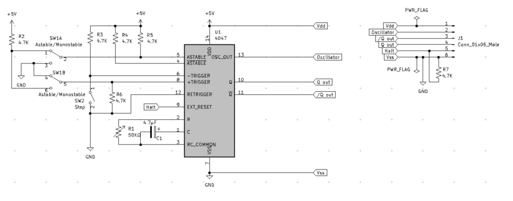
I got to thinking that there must be a simpler way to make a clock source… https://eater.net/8bit/clock and I realized that using anATTINY85 based board seemed a bit of non-retro silliness after a while… So I looked again for a legacy IC-based solution with a lower chip count than 3 LM555s and a few additonal GLUE LOGIC ICs. Keep in mind, this was not because I have a problem with the LM555 clock source from Ben, as this was just an ‘experiment’. After a while of searching through my parts, I found the CD4047 IC. So, here is what I came up with. The best results for me came from using the `Q out pin... but bothe ‘Q’ and ‘/Q’ are available in addition to the OSCILLATOR pin.

Original Drawing
Original Drawing

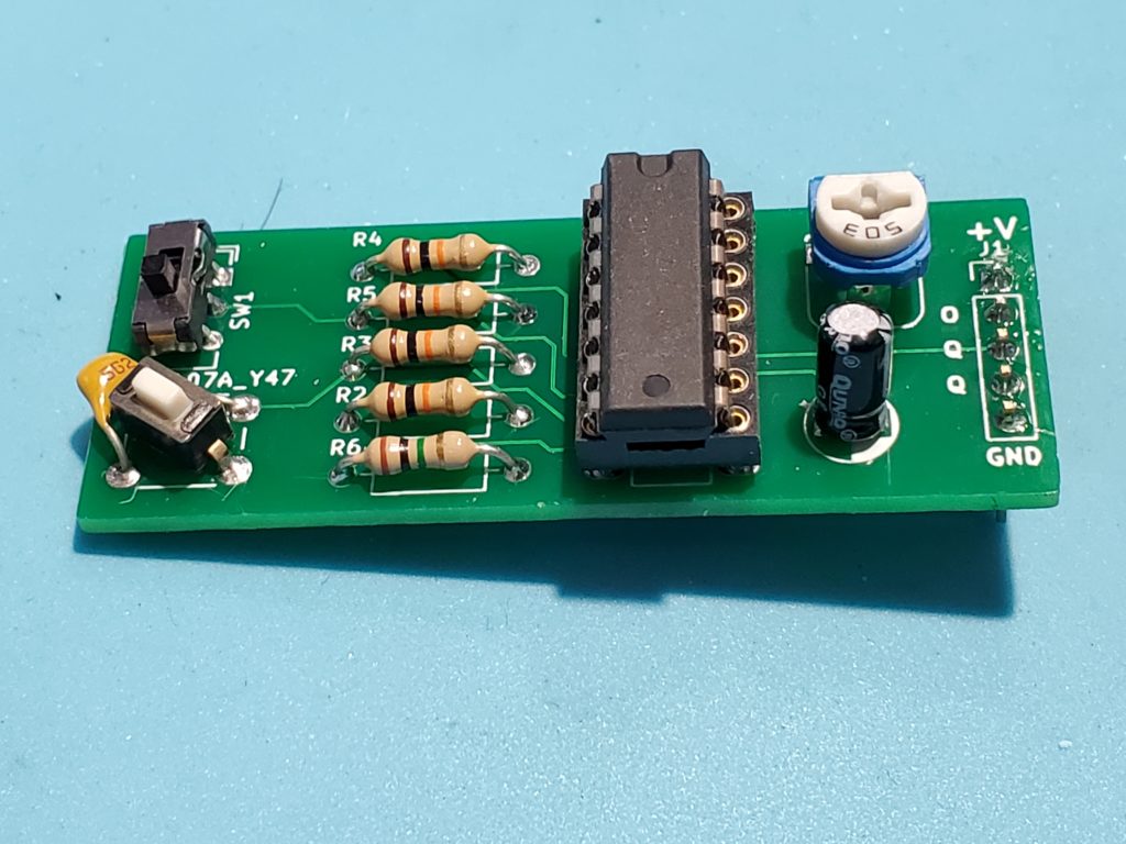
I did get my PCBs… so here is Rev1 with a switch bodge as I need to add a capacitor across the switch for reliable presses. So this is what the CPU clock circuit becomes. Revision 2 will add a Halt feature… and O only needed 1 more resistor.

Yeah… I forgot this existed

Really… I forgot I had a website. Silly me.

WordPress

Have I ever mentioned how much I hate WordPress?

Well, I guess I have now.

CrossCompiling C for Color Computer Code

There is this nice C compiler for the Radio Shack Color Computer now called CMOC. It’s not very easy to get it working under windows and and even with Linux or a MAC it has some involved steps to get it working.

I was recently watching COCO TALK Podcast #43 and they had a discussion about CMOC. Somebody asked if a nice installer existed for it but Boisy Pitre mentioned that it involved some other tools and things to be installed and that made it “complicated”.

This got me thinking… what it it could be a little easier? It got me thinking about a tool called Vagrant. It is a tool that can take advantage of Virtual Machine software like Oracle VirtualBox (which is free). It turned out to be not so hard.

STEP 1

WINDOWS:

Vagrant requires the “Microsoft Visual C++ 2010 SP1 Redistributable Package (x86)” to be installed if you are running Windows. Download it from https://www.microsoft.com/en-us/download/details.aspx?id=8328

Also, windows doesn’t normally have an SSH client… but GITHUB will install one.

In order to get an SSH client on Windows you can install Git. Git is used for version control, but
we’re interested in the SSH client that it ships with. Download git here:
http://mirror.linuxtrainingacademy.com/git/windows/

IMPORTANT: Tell the GIT installer to “USE GIT AND OPTIONAL UNIX TOOLS FROM THE WINDOWS COMMAND PROMPT”… for everything else, take defaults options.

STEP 2

Install VirtualBox from http://mirror.linuxtrainingacademy.com/virtualbox/

Load the right one for your particular operating system. Some versions might require a few extra steps… but the Oracle site has good documentation.

Accept defaults for the installation.

STEP 3

Install Vagrant from http://mirror.linuxtrainingacademy.com/vagrant/

Accept defaults for the installation.

STEP 4

Start a command line session on your local machine. (Windows “Command prompt”, Linux/MAC “Terminal session”

STEP 5

Add A BOX to Vagrant.

A “box” in Vagrant speak is an operating system image. The “vagrant box add ” command will download and store that box on your local system. You only need to download a box once as this image will be cloned when you create a new virtual machine with Vagrant using the box’s name.
I created a box specifically for this solution and uploaded it to the public Vagrant box catalog. Run the following command on your local machine to download it.

vagrant box add pwillard/ubuntu6809cmoc

STEP 6

To work with Vagrant, we need to create a working folder: “mkdir cmoc

Next, we move to that folder: “cd cmoc

Now we need set up out working environment in this folder: “vagrant init pwillard/ubuntu6809cmoc

This will create the local files needed in this folder to refer to the BOX we will be using. So now, its time to bring up our virtual environment. The contents of the “Vagrant” file can be as simple as:

Vagrant.configure("2") do |config|
  config.vm.box = "pwillard/Ubuntu6809cmoc"
  config.vm.box_version = "1.0.0"
end

vagrant up

The first time you run the “vagrant up ” command Vagrant will import (clone) the vagrant box into VirtualBox and start it. If Vagrant detects that the virtual machine already exists in VirtualBox it will simply start it. By default, when the virtual machine is started, it is started in headless mode
meaning there is no UI for the machine visible on your local host machine.

It will do some steps and return to a command prompt. You can check status with:

vagrant status

If the machine is in the “running”state, you are ready to use it.

vagrant ssh

This will open a SSH terminal session to the Linux environment built into the supplied vagrant BOX file. You should see something like the following for a prompt:

vagrant@vagrant-ubuntu-trusty-32:~$

One of the nice features of vagrant is that you can have a shared folder between the vagrant Ubuntu machine and your host PC that is the folder you started the session from. This directory on your PC now has a file in it called Vagrantfile. This is the configuration file for your virtual Linux machine.

You should be able to “cd /vagrant” at the vagrant@vagrant-ubuntu-trusty-32:~$ prompt. You should also be able to see the “Vagrantfile“. If not, you might need to edit the “Vagrantfile” to contain the following line:

config.vm.synced_folder “.”, “/vagrant”, enabled: true

If you needed to add this line, then exit the SSH session, and type: “vagrant reload” and the “vagrant ssh“. You should now have a working shared folder.

With these steps done, you should have a system where you can type handy developer commands like “cmoc“, or “lwasm” or even “decb” and have them actually work. (You didn’t need to install them yourself)

Code

Simple Ways to Write Maintainable Code

Writing maintainable code is something that comes naturally to some and only with a great deal of effort to others. It is within the ability of all programmers though – some just need a little encouragement to drop bad habits. I have been programming for many years now and I have seen a wide range of code which has differed in quality from the horrific train crash style code to the sun drenched gently rolling hillside style.

Over the rest of this part article I will try and describe what I, and many others, feel makes for good and maintainable code. None of the suggestions I will make here are difficult or time consuming to implement and will save many times the amount of time they cost. I am most comfortable when coding in Java so these guidelines have that language in mind. They are equably applicable to any language however.

Simplicity

Simplicity is, in my opinion, the key to maintainable code but simplicity means different things to different people. To me it means that within sixty seconds of looking at a piece of code you should have at least a vague idea what it does. Ideally you should be able to tell roughly what a method is going to do from its signature alone.

I believe simplicity also means avoiding use of obscure or difficult to understand language features unless they are necessary. No language is perfect; they all have aspects that the majority of developers rarely if ever use. Including one of these aspects is just asking for trouble when you or worse a colleague comes to maintain the code. In Java for example you can define static and non-static initialization blocks – how many developers that haven’t taken the Java certification exams even know this is possible? There is also the old ternary operator chestnut – the operator that code maintainers love to hate. I’m not advocating that your code should be the equivalent of a “Spot the Dog Goes to the Beach” children’s book, I believe it should be pitch at or just very slightly above the average developer.

If your code requires you to read volumes of documentation and then study each line in detail there is a good chance that it is too complicated. As with all these guidelines they are just that – guidelines. There are times when a method or piece of code just is complicated but you should aim to minimize these occurrences with good design. Use encapsulation to hide the complexity from the rest of the system and expose a clean and simple interface. Additionally, avoid the mistake of trying to hide complexity by producing hundreds of tiny methods. This is at least as confusing as trawling though one massive method that does all the work.

Aim to make your code as simple as possible and no simpler.

Comments

This will sound like a rather trite statement to make but comment sensibly. Too many comments are as bad, perhaps even worse, than too few. Too many comments and especially trivial comments will cause the maintainer to ignore them. All the effort put into writing the comments is then wasted. Instead comment blocks of code with one line that says what it does. If it needs more than three lines there’s a good chance it’s doing too much.

The one line comment in a method is useful because it means the maintainer can read that and have a pretty good idea whether they can simply skip that section when looking for a problem.

Method level and class level comments can be more verbose. Personally, I like to see thorough documentation of methods that actually do work. Simple getters and setters rarely get commented. Generally a method comment should not describe how the method does something only what it does. In practice if the comments are only intended for internal consumption it can often be useful to add a little information on how as well.

Running a private GITHUB Style service on a Raspberry Pi 3


Using Gitea in Rapberry Pi


Setup

This is a general guide… but it likely needs a few tweaks. It is based on the URL below.

https://hobbylad.wordpress.com/2018/02/16/gitea-git-server-setup-on-raspberry-pi/


Step 1 Setup the USER Account

Create a new user under which the Gitea process runs

sudo adduser --system --shell /bin/bash --gecos 'Gitea user' --group --disabled-password --home /home/git git

Create the required directory structure. Everything is going to be installed in the /home/git/gitea directory.

 sudo mkdir -p /home/git/gitea/{custom,data,indexers,public,log}
 sudo chown git:git /home/git/gitea/{custom,data,indexers,public,log}
 sudo chmod 750 /home/git/gitea/{custom,data,indexers,public,log}
 sudo chown git:git /home/git/gitea


Step 2 Download Gitea

Download the Gitea binary and make it executable.
Check the download page first to figure out the latest version. The second statement is all 1 line.

cd /home/git/gitea

sudo wget -O gitea https://github.com/go-gitea/gitea/releases/download/v1.7.0-rc3/gitea-1.7.0-rc3-linux-arm-7

sudo chmod +x gitea


Step 3 Install a Database Server

We will use MariaDB (MySql) as a database server for Gitea.

sudo apt-get install git mariadb-server
...
sudo mysql -u root -p

grant all on *.* to 'root'@'localhost' identified by 'secretpassword';

MariaDB comes without a PASSWORD on Root. We fix this and then proceed to Gitea tasks.

… Now we create the Database

create database gitea

create user 'gitea'@'localhost' identified by 'gitea';

grant all privileges on gitea . * to 'gitea'@'localhost';

flush privileges;

quit;


Step 4 Run as a Service

So we need to set it up to run as a service:

sudo nano /etc/systemd/system/gitea.service

These lines below tell the service manager how to handle the service, where to start the application and what user to run it under.

[Unit]
Description=Gitea (Git with a cup of tea)
After=syslog.target
After=network.target

[Service]
# Modify these two values and uncomment them if you have
# repos with lots of files and get to HTTP error 500 because of that
#
# LimitMEMLOCK=infinity
# LimitNOFILE=65535

RestartSec=2s
Type=simple
User=git
Group=git
WorkingDirectory=/home/git/gitea
ExecStart=/home/git/gitea/gitea web
Restart=always
Environment=USER=git 
HOME=/home/git

[Install]
WantedBy=multi-user.target


Initialize up the service:

sudo systemctl enable gitea.service

Then…

sudo systemctl start gitea.service


Step 5 Connect to Gitea:

In a browser; http://<Your Host IP or Name>:3000

You will get the option to create a USER and that will kick off the Initial SETUP step , as shown on Hobbylad’s page.

You should probably give the SSH setting the TCP/IP address of the server and the Application URL should have the ‘localhost’ replaced with a fully qualified domain name… this allows you to use the service from other hosts as well.

From here…. it behaves just like github.


GAL/PAL Programming

A potentially lost art from the the early days of Microprocessor based computers.

What is it?

A PAL or GAL is a type of programmable logic gate chip whose basic design goal is to reduce the number of chips on a printed circuit board by allowing a designer to add truth tables to a single chip, thus reducing chip count.


Typical board from the 70’s/80’s era… with lots of TTL Logic ‘glue’.

Boards can be made much smaller, or more dense by reducing the number of ‘black box’ types. In many cases, each of the smaller IC’s on the board above has a dedicated logic function that they offer one or more of. Basically, each chip is designed to perform one type of function.

The PAL, or Programmable Array Logic, and GAL, or Generic Logic Array, are one-time and multi-use re-programmable logic IC that replaces many of these chips on the board. By allowing the logic decisions between inputs and outputs to be customized as needed, these devices are generically called “Programmable Logic Devices, or PLD’s.

By today’s standards, these devices are obsolete as new devices have superseded them far more features and with pins numbering into the hundreds. The Complex PLD (CPLD) is well beyond what will be discussed here. They are programmed in an entirely different way than the legacy PLD devices. PLD’s are programmed in a way very similar to EPROMS and as a result, devices like the affordable TL866 programmer can be used to prepare them.

Pin Assignments in the GAL16V8 – LEFT SIDE are inputs, RIGHT SIDE is outputs

So, how would you use one of these? We can look at an example of where we can replace a few logic IC’s with a single chip. A good example is Grant Searle’s Z80 design. http://searle.hostei.com/grant/z80/SimpleZ80_32K.html

On the web page, there is a diagram of a small but complete Z80 based system. Some logic is used to route memory reads and writes as well as ROM address decoding and such.

I’m talking about replacing U5 and U7 with a single chip. Keep in mind this is an exercise and was picked because it should be pretty easy.

So, if we look at what the chip is doing and how we can apply it to PLD design file… lets examine whats happening.

If you look at the equations on the right, you can see that this is what the 2 chips are accomplishing. (Ignore the system clock portion of U5) By carefully examining the logic of the wiring… this is what we ended up with.

The nest step is to match the Inputs and Output pins to Names that are used in the equations.

The final step is to add the logic (far right column) equations into the programming file.

The resulting file looks like this:

Name     Z80MemDecode ;
PartNo   00 ;
Date     12/27/2018 ;
Revision 01 ;
Designer Pete Willard ;
Company  Personal ;
Assembly None ;
Location  ;
Device   G16V8 ;

/* *************** INPUT PINS *********************/
PIN 2   = !WR                     ; /*   WRITE                         */ 
PIN 3   = !RD                     ; /*   READ                          */ 
PIN 4   = !MREQ                   ; /*   MEMORY REQUEST                */ 
PIN 5   = A13                     ; /*   ADDRESS                       */ 
PIN 6   = A14                     ; /*   ..                            */ 
PIN 7   = A15                     ; /*   ..                            */ 
PIN 8   = !IORQ                   ; /*   INPUT OUTPUT REQUEST          */ 
PIN 9   = !RST                    ; /*   RESET                         */ 

/* *************** OUTPUT PINS *********************/
PIN 19  = !RAMCE                  ; /*  RAM Chip Enable                */ 
PIN 18  = !ROMCE                  ; /*  ROM Chip Enable                */ 
PIN 17  = !MEMRD                  ; /*  Memory  Read                   */ 
PIN 16  = !RAMWE                  ; /*  RAM Write                      */ 
PIN 15  = IOREQUEST               ; /*                                 */ 
PIN 14  = RESET                   ; /*                                 */ 

/* *************** LOGIC EQU  *********************/
RAMCE       = !A15                 ; /*                                 */ 
ROMCE       = A13 # A14 # A15      ; /*                                 */ 
MEMRD       = MREQ # RD            ; /*                                 */ 
RAMWE       = MREQ # WR            ; /*                                 */ 
IOREQUEST   = !IORQ                ; /*                                 */ 
RESET       = !RST                 ; /*                                 */ 


In order to program a GAL the source file (“.pld”) must be transformed into a JEDEC file. The resulting JEDEC file uses the filename suffix of JED. This is the file that is used by the TL866 Programmer to prepare the device according to our design.

The editor used to create the specification (PLD) and JED file is called WINCUPL, which is a free tool made a available by ATMEL and still offered by the company acquired ATMEL, Microchip.

Here is the link: https://www.microchip.com/design-centers/programmable-logic/spld-cpld/tools/software/wincupl

So… DID IT WORK? Nope !

It turns out… WINCUPL has issues with NEGATIVE OUTPUT LOGIC in equations. So… back to the drawing board… I’ll provide a fix later…