This is a variation of many many other LC meters already published. It owes much of it’s design to the AADE LC meter that relies on the oscillation of a standard Analog Comparator using a capacitor and a coil. This solution is an attempt to take Kerry Wong’s Arduino implementation and simplify it a bit and to make use of latching relay for mode selection.
Notes: Initially I used a 2% tolerance .001uF capacitor and a small 5% tolerance RFC 220uH coil. results were OK, but not real close to actual values even after some tweaks so I looked for an alternative in my junk box.
I found a 1800pF Mica capacitor with 1% tolerance and a 82uH radial choke coil (Basically, the kind used in higher current situations). I did some quick math and determined that frequency of oscillation would increase to somewhere between 414473 HZ and 419973 HZ with the former being the mathematical ideal. (which I modded to an even 420000 for simplicity.)
My changes (completed and planned) to the Kerry Wong’s solution includes:
1) Software controlled backlight – no switch – I just turn it on… that works for now
2) Implementation of Latching Relay to eliminate a DPDT manual switch
3) Using an 8×2 LCD for smaller footprint
4) Battery Voltage sensing. If battery is low, shut off the backlight.
5) Push-on/push off power control with timer based auto shutoff. (5 minutes)
Testing showed me that I really didn’t like using the KHM Library from Martin Nawrath. I mean, it basically worked and that is what Kerry Wong used… but, I found that it was impacting my mode switch and calibrate button sensing. And that was just not good now that I was using a latching relay instead of a DPDT switch for mode change.
In the end, I opted for the Frequency counting library from PJRC instead:
Sprint Layout File:
Sprint Layout (V6)
Schematic:

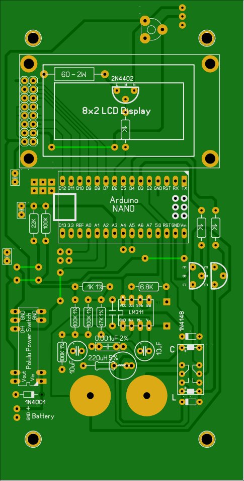
Layout (only 2 minor errors crept in during etching):
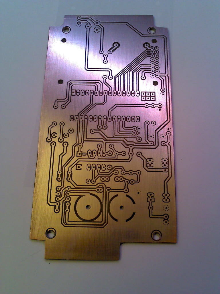
Etched PCB (tinned and sealed with matte clear laquer AKA Dullcote):
Silkscreen: Toner Transfer to TOP SIDE PCB, sealed with Future floor wax (clear acrylic)

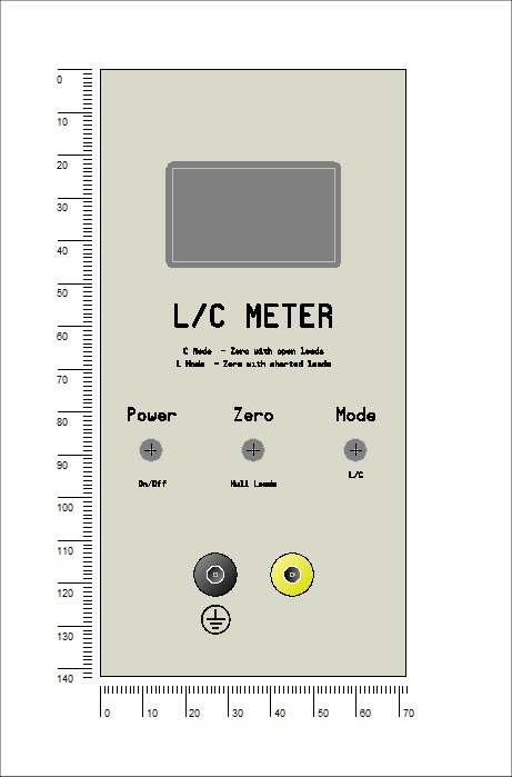
Front Panel:
Hi dear friend
I have a problem, I can’t change the mode, is there any issue that I don’t know ?
Please, help me !
There is not an impulse going from arduino’s D4.
Regards
Arnold
Dear Friend,
I tried to build the same scheme as you suggested, I done all you wrote, but unfortunately it doesn’t work. Please help me, I think there isn’t an impulse for communication with relay, the impulse from D3 goes, but from D4 doesn’t.
Regards
Arnold