One way that I get reliable 1-wire communication is to use a power injector. This means that the along with the 1-wire signals, I inject a supply voltage into additional cable pairs.  Since  the most readily available commodity cable currently is 8 conductor Cat-5 cable, chances are that you also use this cable for 1-wire cabling and have spare wires going unused. Dallas called the 1-wire bus a MicroLAN, so I will continue to use their terminology here.
For short runs, where the total length of the MicroLAN is < 30 meters and the network only has maybe 6 to 10 slave devices on it, cable selection for use on the MicroLAN is reasonably simple, as even flat modular phone cable can work with a small numbers of 1-Wire slave devices. However, the longer the MicroLAN, the more important cable properties and therefore cable selection becomes more critical.  However, since I’m dealing with 30M or less, I’ll focus on that here and leave the research for  better cable techniques for when I run into a problem.
One of the remaining issues with using 1-wire driven from an Arduino pin directly is the fact that it is also providing power to all of the devices on the the 1-wire LAN when in parasitic mode.  While 1 or 2 devices are of little concern, I started to worry about building a reliable 24/7 full time  MicroLan configuration that would report weather data from 8 or so sensors, most of which were located at the garden bed outdoors.  It became clear that some of my devices were really not performing as desired  when “parasitically”  powered when I finally put all the pieces together.
Experimentation showed me that the signal from the Arduino pin was just not up to that task of powering and communicating with all the devices without some random miscommunication here and there. Â I would get values like 185F and not the 70F I was expecting from a 1-wire temperature sensor, for example.
My solution was reasonably simple. Â I would create an external “middle-man” device that would insert power into the CAT-5 cable after leaving the Arduino board. Â Its really just a dual supply from typical commodity wal-wart power source. Â The unmodified 12VDC supply will be fed into the cable on a spare pair and treated as “unregulated” and a 5V regulator will be added to another spare pair and considered to be “regulated”. Â All code will now be written to comply with the “non-parasitic” mode of 1-wire.
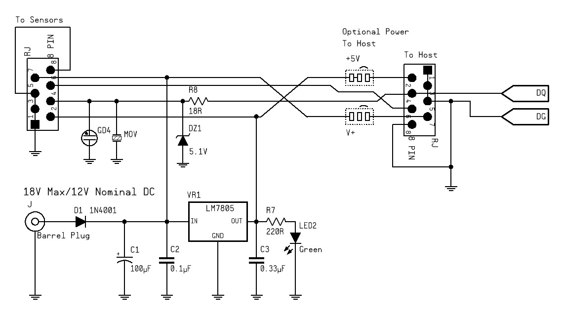
The Design:
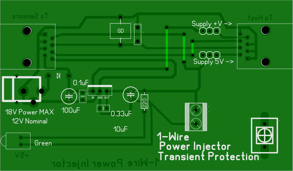
The PCB: