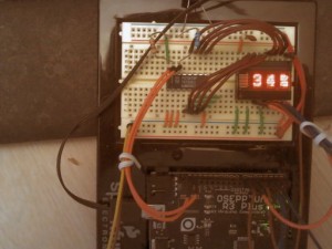
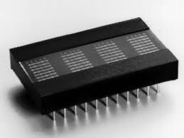
This information has been collecting dust on my hard drive. Time to resurrect it… Recently I have been working on a Temperature and Humidity display and while working on it, decided to use these RETRO parts I got from BGMICRO sometime around 2000. Even then, these parts were considered “pure unobtanium”. I still had a few leftover displays, so out from the parts collection they come.
Now I had never taken the time to really get these displays working on an Arduino and what I really wanted was a test that would show off how much information you can really show using only 4 characters.
Since this project was to be inserted into an already working sketch, I made sure it was as modular as possible, sprinkled with subroutines that could be called from “who knows where” to get the job done.
I’ve tried to comment where it made sense and I have drawn up a quick schematic drawing to show just how its connected. Since this part was designed for a CPU Bus Architecture of the 70’s and 80’s, it is annoying to see how demanding it is of the limited pin resources on the Arduino. The display assumes you provide data in a Parallel 8-bit format. To relax this demand for pins, I employed a PCF8574 ( I2C port expander) that was harvested from some abandoned electronic board. “YAY for recycling!”
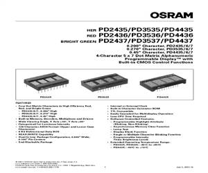
The parts I’m talking about are the PD243x displays from OSRAM.
So, what we have here is some sample code, for the Arduino, that allows you to send ASCII strings (including text scrolling) to these vintage displays. Some of the information that helped me get beyond the datasheet was gathered from around the Internet (including blogs in New York, Japan and Korea) Kudo’s to TechBlog in Korea for creating such a great resource.
Interesting side story: WAY BACK WHEN… BG Micro had horrible 3rd party photocopies of a facsimile for these parts. They were almost entirely unreadable. At the time, datasheets were generally unavailable on the Internet, so, after spending hours searching with “Altavista”, I finally found a clean PDF copy of the datasheet. Rather than just keep them to myself, I decided to give a nice clean datasheet back to BG Micro so they could share it with other customers who purchased the parts.
CODE
//==============================================================================
// PPPP  DDDD  2222  4  4  3333  77777        III  N   N OOOOO
// P   P D   D     2 4  4      3    7          I   NN  N O   O
// PPPP  D   D  222  44444  333    7           I   N N N O   O
// P     D   D 2        4      3  7     ..     I   N  NN O   O
// P     DDDD  22222    4  3333  7      ..    III  N   N OOOOO
//==============================================================================

//==============================================================================
// Program:      PD2437.ino
// Author:       Pete Willard
// Version:      0.01
// Target:       328p IDE 1.03
// Date:         2013/01/27
// Time:         12:00:18
// Notes:

// This program is free software: you can redistribute it and/or modify
// it under the terms of the GNU General Public License as published by
// the Free Software Foundation, either version 3 of the License, or
// (at your option) any later version.

// This program is distributed in the hope that it will be useful,
// but WITHOUT ANY WARRANTY; without even the implied warranty of
// MERCHANTABILITY or FITNESS FOR A PARTICULAR PURPOSE.  See the
// GNU General Public License for more details.

// You should have received a copy of the GNU General Public License
// along with this program.  If not, see <http://www.gnu.org/licenses/>.

// Reference: "nautes Tech Blog", "David Croft @ davidc.net"
//==============================================================================

//=====[ INCLUDE ]==============================================================
#include stdlib.h
#include Wire.h
//=====[ CONSTANTS ]============================================================
#define   DEBUG     1   // 0 = debugging disabled, 1 = enabled
// Address of PCF8574 IC on TWI bus is address 0100xxx (0x20)
// while the PCF857A address is 0111xxx. (0x38)
#define IO_ADDR (0x20)

//=====[ PINS ]=================================================================
int Led = 13;  // Not used
// Connected to PD2437 directly
int PA0 = 2;   // Address 0 (pin 9)
int PA1 = 3;   // Address 1 (pin 8)
int PA2 = 4;   // Address 2 (pin 7)
//
int WR = 7;   // Write (pin 7)
int CE = 5;   // Chip Enable (pin 6)
int RST = 6;  // Reset (NEG, pin 11)
//=====[ VARIABLES ]============================================================
char messagebuffer[21];

//=====[ SETUP ]================================================================
void setup()                    // run once, when the sketch starts
{
	Serial.begin(9600);
	Wire.begin();        // initialize the I2C/TWI interface

	// Setup pins for PD2437
	pinMode(PA0, OUTPUT);
	pinMode(PA1, OUTPUT);
	pinMode(PA2, OUTPUT);
	pinMode(WR, OUTPUT);
	pinMode(CE, OUTPUT);
	pinMode(RST, OUTPUT);

	// Reset PD2437
	digitalWrite(CE, HIGH);
	digitalWrite(WR, HIGH);
	digitalWrite(RST, LOW);
	digitalWrite(RST,HIGH);
	AsciiMode();
}
//==============================================================================

//=====[ LOOP ]=================================================================
void loop()                     // run over and over again
{

	// Can do this...
	char messagebuffer[] = "  Temperature: 68F  ";
	ClearDisplay();
	ScrollDisplay(messagebuffer);
	delay(1000);

	// Random Length String with INT value added
	int n = 34;
	sprintf(messagebuffer,"   Humidity: %2d%%  ",n);
	ClearDisplay();
	ScrollDisplay(messagebuffer);
	delay(1000);

}

//==============================================================================
//=====[ SUBROUTINES ]==========================================================
//==============================================================================

void CommandMode(){
	digitalWrite(PA2, LOW);  // enable command mode
}
//==============================================================================

void AsciiMode(){
	digitalWrite(PA2, HIGH);  // enable ASCII mode
}
//==============================================================================

void TogglePin(char bitpin) {
	digitalWrite(bitpin,!digitalRead(bitpin));
}
//==============================================================================

void PulsePin(char bitpin) {
	TogglePin(bitpin);
	TogglePin(bitpin);
}
//==============================================================================

void ClearDisplay() {
	CommandMode();
	PutChar(0, 0x83);
	delay(100);
	AsciiMode();

}

//==============================================================================
// Note: This looks funny because it reads the buffer from right to left
// Blame the display...  :-P

void WriteDisplay(char *input) {
	for (int i=0; i<4; i++) {
		PutChar(i, input[3-i]);
	}
	input = "";
}
//==============================================================================

void SetByte(int ch) {
	// Use TWI output Mode to Write to DATA BUS PINS on PD243x
	Wire.beginTransmission(IO_ADDR);
	Wire.write(ch);
	Wire.endTransmission();
}
//==============================================================================
// set address for PD243x

void SetAddr(int adr) {
	digitalWrite(PA0, (adr&0x1));
	digitalWrite(PA1, (adr&0x2));
}
//==============================================================================
// Main Character writing routine

void PutChar(int pos, int ch) {
	SetByte(ch);			// Pre-set the 8 bit data bus
	SetAddr(pos);			// pre-set the address bus
	digitalWrite(CE, LOW);	// Enable Display
	PulsePin(WR);  			// Read inputs and display it
	digitalWrite(CE, HIGH);	// Disable Diplay
}
//==============================================================================

void ScrollDisplay(char *ascii) {
	char buffer[4];
	int i = 0;
	boolean blank;
	while(ascii[i] != 0){
		blank = false;
		for (int ii = 0; ii<4; ii++) {
			if ( !blank && ascii[i + ii] == 0 ) {
				blank = true;
			}

			if ( blank ) {
				buffer[ii] = ' ';
			}
			else {
				buffer[ii] = ascii[i + ii];
			}
		}
		buffer[5]=0;
		WriteDisplay(buffer);
		delay(250);
		i++;
	}
}


Thanks for gathering this information. I have a few of these displays my dad picked up from Tammy at BG micro years ago. We never could get these to work (and yes the data sheets were poor quality)but this arduino has resparked the hobby for us.
Kudos to you.
Hello, I seem to find myself with about 200 PD2435 which need a good home to be used in a project like the one above. If you need any please contact me.
rjwright5555@gmail.com