Author Archives: myadmin

Selector Switch with ARDUINO

A fellow Arduino guy from Texas asked about how to set up a multi-mode selector switch using a single pushbutton and 3 states (not including the boot up state). What follows is this discussion that we had becoming a back and forth collaboration of ideas until I got off work and decided to see if I could make it more robust and simpler at the same time.

Lets talk about the original code…  it essentially worked… with some quirks.

The original code would continuously set all the pins… every loop, even though it didn’t need to…

It also tried to process the loop even if the mode was equal to zero (IE; No button presses have occurred yet and in that case, all LED’s should be off)

Lastly, it got weird when mode was incremented to 4 and set back to 1 and in here is the behavior that I wanted to eliminate.  It would change to mode 1 and 2 and 3 when the key was PRESSED but would only go back to mode 1 when button was released when in mode 3.  This is just not the way to make all the button presses seem similar.  All the other buttons react on the button press, not the release.

So it was SWITCH/CASE to the rescue.  With switch case statements I could handle all the mode switching and deal with mode 1 and any other mode that was not 2 or 3 with the default statement.  This allowed it to have all button mode migration to appear to behave the same.

The code also makes sure that pins do not get changed when they don’t need to be… IE; every loop traversal.

On to the final code example…

/*
 Using a single switch to select between 3 modes
*/
// Schematic: http://www.pwillard.com/files/mode4.jpg
//===============================================================
// Global Variables & Constants
//===============================================================

const int ledPinOne = 2; // LED1 ANODE
const int ledPinTwo = 4; // LED2 ANODE
const int ledPinThree = 7; // LED3 ANODE
const int modePin = 13; // Active HIGH, held low by 4.7K

int mode = 0; // Selector State (Initial state = ALL OFF)
int val = 0; // Pin 13 HIGH/LOW Status
int butState = 0; // Last Button State
int modeState = 0; // Last Mode State
boolean debug = 1; // 1 = Print Serial Enabled / 0 = disabled

//===============================================================
// SETUP
//===============================================================
void setup () {
 pinMode(ledPinOne, OUTPUT);
 pinMode(ledPinTwo, OUTPUT);
 pinMode(ledPinThree, OUTPUT);
 pinMode(modePin, INPUT);
 if (debug){
 Serial.begin(9600);
 Serial.print("Initial Mode: ");
 Serial.println(mode);
 Serial.print("Setup Complete\n");
 }
}

//===============================================================
// Main Loop
//===============================================================
void loop() {

 val = digitalRead(modePin);

 // If we see a change in button state, increment mode value
 if (val != butState && val == HIGH){
 mode++;
 }

 butState = val; // Keep track of most recent button state

 // No need to keep setting pins *every* loop
 if (modeState != mode){

 // If no keys have been pressed yet don't execute
 // the switch code below
 // if (mode != 0) {

 switch ( mode ) {
 //case 1 is actually handled below as default

case 2:
 digitalWrite(ledPinOne, LOW);
 digitalWrite(ledPinTwo, HIGH);
 showState();
 break;
 case 3:
 digitalWrite(ledPinTwo, LOW);
 digitalWrite(ledPinThree, HIGH);
 showState();
 break;
 default:
 mode = 1;
 // loop back to 1 by default, seems redundant but
 // it also handles the "mode is > 3" problem
 digitalWrite(ledPinThree, LOW);
 digitalWrite(ledPinOne, HIGH);
 showState();
 break;
 } // end switch
// } // end of "if mode = 0" check
 } // end of ModeState check
 modeState = mode; // Keep track of mode recent mode value
 delay(10); // slow the loop just a bit for debounce
}

//===============================================================
// Subroutine
//===============================================================
void showState() {
 if (debug){
 Serial.print("Mode: ");
 Serial.println(mode);
 }
}

Tagged

Current Weather Station

Arduino Mega

AAG One Wire Weather Instrument Series 2. (Wind Speed, Temperature, Wind Direction)  DS18B20 temperature, DS2423 (wind speed) DS2450(wind vector)

Hobby Boards: Humidity/Temperature Board – Built from my own parts

Rain Gauge (See my post about it)

BMP085 – Pressure Sensor

Internal Temperature via DS18B20

1-Wire Power Injector (see my “how to make a PCB guide):

In progress: COSM upload – nope.

FAIL:  Adding COSM/PACHUBE support ran me out of working RAM… so project for upload of data is scrapped at the moment.

Updated Rain Gauge

Newest Rain Counter

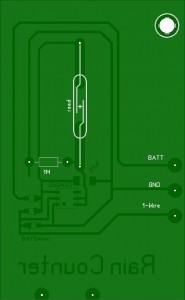
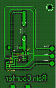
So I’m taking the time to re-do the rain gauge. The existing one clearly had some issues (hacks/fixes) and I wanted to also gain the use of counter B (if possible) for a different piece of weather gear.

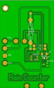
Rain Counter version 7

I was also able to get a hold of some “liquid tin” from MG Chemicals to see if it compares well to Cool-AMP powder as a copper plating solution.

Results:

While the Liquid Tin is much easier to apply, I actually don’t like it as much as the Cool-Amp coating.

Weather Station – Hacked Rain Gauge

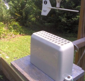
Converting a broken  LaCrosse WS-9004U 915MHz WIRELESS RAIN GAUGE into a “wired” 1-wire  0.02 inches per tip rain gauge.

The Lacrosse unit is an inexpensive rain gauge available from my local Fry’s store for about $24.  They are unusually finicky when being set up so I already knew I didn’t really have a lot of love for the device.  After about 6 months, my unit stopped sending/receiving updates and no amount of new batteries, resets or pairing attempts seemed to help.  I tossed it into my junkbox of parts.

Right around the time that MAXIM decided that making 1-wire devices was “tooo haaarrd”, (said in a whiner voice) and they killed off the DS2423 counter device, I decided to buy some before they were totally gone to see if I could make my junkbox tipping bucket hardware work in a “wired” mode.

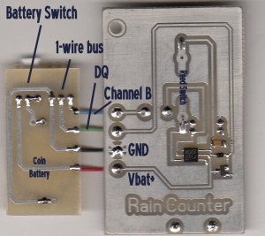
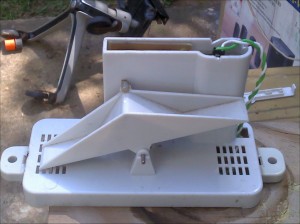
It wasn’t really that hard.  I used a sample design from my WEATHERTOYS book, (AUTHOR: Tim Bitson), and  after ripping all the guts out of the device (wireless sender and battery holder, I had some room for some 1-wire related parts.

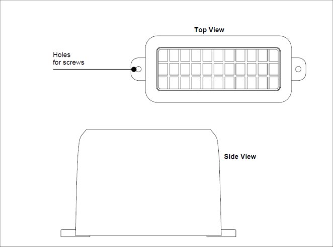
The original PCB  fits in a nice slot in the plastic case and used a reed switch aligned with a magnet attached to the center of the tipping bucket.  I used the dimensions to create a replacement board and everything fit except the CR2032 battery needed by the counter to not lose data when 1-wire was shorted or disconnected.

Original Board:

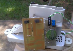
The CR2032 nicely fit into the area where the prior AAA batteries were housed.

The 1-wire connection is made by using a weatherproof gel-filled crimp splice available from the local hardware store.

The code (java in my case) is straight from the Weathertoys book with adjustments made relating to the side of the tip, 0.02 inches per tip.

Installation

The Guts

The main board and battery board

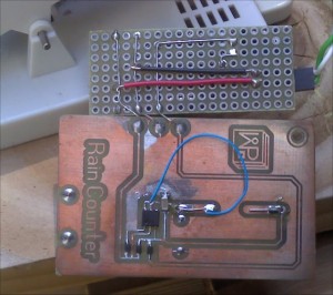
The backside

Note: Not my best work…  I attempted to re-orient the reed switch during testing, which only managed to a) break a reed switch and b) break a copper trace (fixed with blue wire).  In addition, I actually installed the wrong SMD part that I thought was a DS2423… which turned out not to be the case…

I suppose I could make a new board… but once this one started working… I just left it alone.

The gauge is currently off the station since I forgot to paint the plank, made from ash, used to mount the sensor.  Small ants were using the aging cellulose to create a fungus garden under the cover of the rain collector.  Silly me.  Now I must replace and paint the replacement wooden board.

Next Step.  Stop using a Linux server and JAVA and convert over to an Arduino  MEGA2560 as a weather station controller.

Weather Station Woes

I might have mentioned that my AAG WS603B Weather Station turned out to be the most oddball replacement for my original 1990’s Dallas 1-wire Weather instrument.  It worked reliably for 10 years.  I had version 1.0, which was rather difficult to program for as it used the DS2401 serial number for each wind direction.  This required a lot of extra  1-wire coding.

I’ll spare you some of  the gory details regarding the quality of the latest AAG unit though I should mention that it was incompatible with all 1-wire wiring standards to date.

The real problem with the new unit (other than reliability) was that the new case is clear (no so bad) full of colored LED’s (can you say SILLY?) and not water resistant. Even though the case seemed closed and the PC board was “sealed”, it still managed to die after 6 months of usage.   It took 6 months of trying to get the Windows software from them for the station… by then… the device was dead. I’ll not be buying anything else from AAG.

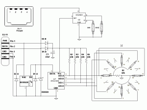
Anyway, one of the design ideas that AAG implemented was actually quite sensible. They used HALL sensors for Wind Direction instead of the fragile reed switches as used with other station designs. The Dallas Version 2 weather station (formerly sold by AAG) used a DS2450 and reed switches to track 16 positions of wind direction with just 1 magnet rotating. Only 8 sensors were needed as the intermediate positions were resolved when the magnet straddled two sensors at once.

Dallas Weatherstation version 2 Schematic:

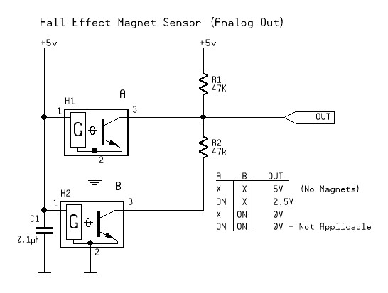
I attempted to recreate this solution with Hall Effect Sensors. My first test circuit is below. Seems to work well.

So now my plan is to rebuild a replacement for the failed board in the WS603 housing.

Creating a weather station with Linux

Long ago I decided that I wanted to keep track of local weather. This is somewhat related to my desire to keep an eye on my raised bed gardens during the summer and partially due to my desire to have fun electronics projects to keep me doing “fun things”. I had already started with 1-wire and had a few devices that I either purchased or made myself.

As a first pass, I decided to see if I could get all my sensors working under Linux before attempting the Arduino weather station  conversion.  That said, It would have been easier if I had decided to use Windows and follow Tim Bitson’s examples from his “Weather Toys” book. The book provides guidance for MacOS and Windows only. That’s really not a show stopper though as I was able to get everything working.

Step 1: Install Linux

Install Ubuntu Linux workstation version 9.10 LTS (I tried newer versions but they have some annoying issues)

Step 2: Installing JavaVM and RXTX

Note: A version of Java is installed by default, It’s just not the one I want.

I installed the full suite of latest SUN JAVA (not default OPENJDK and note that the SUN install requires enabling partner repositories – Google for instructions about enabling and then the JAVA install is simple)

Install RXTX with the command

sudo apt-get install librxtx-java

(It does all the tricky bits for you)

Step 3: OneWire support for JAVA

Download OneWireAPI “http://files.dalsemi.com/auto_id/public/owapi_1_10.zip
Extract contents  to a convenient location and get setup to copy files.
Copy the file OneWireAPI.jar to /usr/share/java/OneWireAPI.jar

The Java Libraries get installed to /usr/share/java. This is default behavior for librxtx-java install, so I used the same solution for OnewireAPI (manually copied)

Step 4: NETBEANS

In my case, this is version 6.8, installed from Synaptic Installer or you could use:

sudo apt-get install netbeans

Netbeans will create a project directory by default in your home folder. Your code goes here.

Libraries:
When defining the library settings for NETBEANS, it’s as simple as the two entries in the “libraries” section, as shown in the book.
a) /usr/share/java/OneWireAPI.jar
b) /usr/share/java/RXTXcomm.jar

Step 5: Grab WEATHERTOYS code.

Here

General Notes

I use the AAG TAI603B interface (USB-SERIAL & 1 Wire Power Injector with home made Hobby Boards adapter) and this is automatically recognized as a device by this version of Linux. In my case, it is a serial device, coded as:

public static final String ONE_WIRE_SERIAL_PORT = "/dev/ttyUSB0";

and seen by the API as:

public static final String ADAPTER_TYPE = "DS9097U";

You can find the ports available with the following command:

sudo dmesg | grep tty

You will likely see something like:

"/dev/ttys0" or  "/dev/ttyUSB0"

Barometric Pressure

While looking at low cost pressure sensors in the Mouser Electronics catalog, I located the FREESCALE MPXAZ6115A as a possible sensor for my project. The sensor has the following statistics;

Device: MPX6115, MAX PSI 16.7, MAX kPa 115.

Since barometric pressure here hovers at around 100kPa or so, this sensor would do just fine. The analog output of the sensor is relative to the min/max pressure range of the sensor.

According to my initial tests, the sensor would output about 4.06 volts at 100kPa.

The built-in analog input on the Arduino would also keep the circuit simple and after a few tests I was able to determine the offset value I needed to get correct readings for the localized barometric pressure.
In my case… testing showed that the magic number is 0.13.

// Nominal Transfer Value:
// Vout = VS x (0.009 x P – 0.095)
// ± (Pressure Error x Temp. Factor x 0.009 x VS)
// VS = 5.1 ± 0.25 Vdc

float Vin;
float P;

void setup()
{
Serial.begin(9600);
}

void loop()
{
Vin = (5.0/1024.0) * analogRead(0);
Vin = Vin + 0.13;     // Offset Adjustment
 Serial.print(Vin);
 Serial.println(" Volts");

P=((Vin/5.0)+0.095)/0.009;
 Serial.print(P);
 Serial.println(" kPa");

Vin = (P * 0.2952999);
 Serial.print(Vin);
 Serial.println(" Inches of Mercury");
delay(2000);
}

I’m using a LADYADA Boarduino on a solder-less breadboard for testing. The sensor hookup is dead simple with only one exception that makes it tricky. The part I selected is designed to be surface mounted.

I decided to create a carrier board using the board layout software I prefer called SprintLayout from ABACOM in Germany. Other than 5V power and ground connections, the Vout from the carrier board goes directly to the Arduino Analog(0) pin.

To create the PCB board, I use the GOOTIE toner transfer method to apply the layout on the PCB for etching. (google search “gootie PCB” for more info)

Having developed a dislike for the chemical etchant that Radio Shack sells; Ferric Chloride, I have also adopted the etchant that
Gootie describes.

It is based on the swimming pool chemical Muratic Acid and Hydrogen Peroxide in a 1 to 2 ratio. It’s fast, non-opaque and does not require heating or excessive agitation.

Note: I also recently picked up a used GBC Creative Laminator at the local Goodwill for $14.00. It does an excellent job of applying the toner to the copper on the PCB to be etched. Using an hand iron was OK, but the results were not always predictable.

My method of making PCB’s at home.


Here is the Layout:

Legacy Recovery: Arduino and Parallax SHT-11 BoB

July 3, 2008

As a part of my ongoing project and seemingly never ending interest in what’s going on outside my window, I purchased a a PARALLAX humidity and temperature sensor.  Basically, the Parallax part is a surface mount  Sensirion Temperature/Humidity Sensor nicely mounted on a PC board that has 8-PIN DIL pin out for insertion into a solder-less breadboard.

It’s available from MOUSER and from PARALLAX directly.

To get it working, the circuit itself is dead easy.  The Parallax part has additional SMD pullups and capacitors right in the 8-pin DIL package so we are only dealing with a few wires.  I don’t even need to really show a schematic… the details are in the code.

The code is not really my own creation at all.  It is a collection of good ideas from others who have already dealt with this device.

   
//==========================================================================//
//                                                                          //
//   SHT-11 Humidity & Temperature      Version 1.00     December 2008      //
//                                                                          //
//   NOTICE:  This is for ARDUINO IDE VERSION 18!                           //
//   Some methods used are no longer needed.                                //
//                                                                          //
//   Written for the Arduino ATmega168 Diecimila and installed and tested   //
//   on December 12,2008                                                    //
//                                                                          //
//   Multiple Internet references were used, combined and modified          //
//   for this example, such as Arduino forums and nuelectronics.com         //
//                                                                          //
//==========================================================================//
// Devices Used:                                                            //
// Boarduino:  USB Powered - Diecimila                                      //
// http://www.ladyada.net/make/boarduino/index.html                         //
// The Boarduino is a Solderless Breadboard compatible Arduino              //
//                                                                          //
// Parallax Sensirion SHT-11 module                                         //
// http://www.parallax.com   (Look for    "SensirionDocs.pdf" )             //
//                                                                          //
//                  The parallax module is a breadboard compatible carrier  //
//                  with the SMD sensor installed by parallax               //
//                  NOTE: Different Pinout than SMD sensor from Sensirion   //
//==========================================================================//
// Notes:                                                                   //
//                                                                          //
// The Parallax module contains built-in Pullup and  Data Pin resistors     //
// Sensor Carrier     Boarduino                                             //
// Data Pin 1   --   Arduino pin 10                                         //
// Clock Pin 3  --   Arduino pin 11                                         //
// Vss Pin 4    --   Arduino GND                                            //
// Vdd Pin 8    --   Arduino 5V                                             //
//==========================================================================//

//==========================================================================//
//                            Preamble                                      //
//==========================================================================//
#define  LED 13

#define  T_CMD  0x03                // See Sensirion Data sheet
#define  H_CMD  0x05
#define  R_STAT 0x07
#define  W_STAT 0x06
#define  RST_CMD 0x1E

//==========================================================================//
// SHT11 Sensor Coefficients from Sesirion Data Sheet
const float C1=-4.0;               // for 12 Bit
const float C2= 0.0405;            // for 12 Bit
const float C3=-0.0000028;         // for 12 Bit
//const float D1=-40.0;              // for 14 Bit @ 5V
//const float D2=0.01;               // for 14 Bit DEGC
const float T1=0.01;               // for 14 Bit @ 5V
const float T2=0.00008;            // for 14 Bit @ 5V
//==========================================================================//
// Sensor Variables
int shtClk   =  11;                // Clock Pin
int shtData  =  10;                // Data Pin
int ioByte;                        // data transfer global -  DATA
int ackBit;                        // data transfer glocal  - ACKNOWLEDGE
float retVal;                      // Raw return value from SHT-11
float temp_degC;                   // working temperature
float temp_degF;                   // working tempeature
float r_temp;                      // raw working temp
float r_humid;                     // Raw working humidity
float dew_point;
float dew_pointF;
//==========================================================================//
// coding variables
int dly;
int timewait;
byte bitmask;

//==========================================================================//
//                                                                          //
//                            Code Body                                     //
//                                                                          //
//==========================================================================//

void setup()

{
    
    
    pinMode(shtClk, OUTPUT);        // Initialize the pins
    digitalWrite(shtClk, HIGH);     // Clock
    pinMode(shtData, OUTPUT);       // Data
    pinMode(LED, OUTPUT);           // LED
    Serial.begin(9600);             // open serial Port for 9600 Baud
    
    Serial.println("Resetting Sensor..");
    SHT_Connection_Reset();
    
    // Fast Flash LED to say we are ready
    digitalWrite(LED, HIGH);
    delay(500);
    digitalWrite(LED, LOW);
    delay(500);
    digitalWrite(LED, HIGH);
    delay(500);
    digitalWrite(LED, LOW);
    //-----------------------------
    
    Serial.println("Starting Temperature & Humidity reading every 5 seconds.");
    
}


//==========================================================================//
void loop()
//==========================================================================//

{
 // SHT-11 Get Temperature
    
    Serial.println("------------------------------------------------------------------------------");

    SHT_Measure(T_CMD);                    // retVal = Temperature reading
    r_temp = retVal;
    
    temp_degC = SHT_calc_tempC( retVal);  // Convert to Celcius
    Serial.print("Temperature: ");
    serialPrintFloat(temp_degC);
    Serial.print("C");
    Serial.print('\t');
    
    temp_degF = SHT_calc_tempF( retVal);  // Convert to Fahrenheit
    Serial.print("| Temperature: ");;
    serialPrintFloat(temp_degF);
    Serial.print("F");
    Serial.print('\t');
    Serial.println();

    // SHT-11 Get Humidity
    SHT_Measure(H_CMD);                     // retVal = humidity reading
    r_humid = retVal;                       // Store raw humidity value
    Serial.print("Humidity: ");

    // Linear conversion
    float rh_lin = C3 * retVal * retVal + C2 * retVal + C1;

    // Temperature compensated RH
    float rh_true = (temp_degC * (T1 + T2 * retVal) + rh_lin);
    if(rh_true>100)rh_true=100;       // deal with rh being outside
    if(rh_true<0.1)rh_true=0.1;       // a physical possible range
    serialPrintFloat(rh_true);
    Serial.print("%");
    Serial.print('\t');

    // calculate Dew Point
    dew_point=calc_dewpoint(rh_true,temp_degC); //calculate dew point
    dew_pointF = 9 * dew_point/5 + 32;
    
    Serial.print("| Dew point:   ");
    serialPrintFloat(dew_point);
    Serial.print("C");
    Serial.print("   ");
    serialPrintFloat(dew_pointF);
    Serial.print("F");
    
    Serial.println();
    
    // Slow Flash activity LED and create pause between scans
    //  ...in this case, 5 secs)
    timewait = 0;
    while (timewait < 5)
    {
        
        digitalWrite(LED, HIGH);
        delay(500);
        digitalWrite(LED, LOW);
        delay(500);
        timewait++;
        
    }
}


//--[ Subroutines ]---------------------------------------------------
void SHT_Write_Byte(void)
{

    pinMode(shtData, OUTPUT);
    shiftOut(shtData, shtClk, MSBFIRST, ioByte);
    pinMode(shtData, INPUT);
    digitalWrite(shtData, LOW);
    digitalWrite(shtClk, LOW);
    digitalWrite(shtClk, HIGH);
    ackBit = digitalRead(shtData);
    digitalWrite(shtClk, LOW);
    
}

//--------------------------------------------------------------------
int shiftIn()
{

    int cwt;
    cwt=0;
    bitmask=128;
    while (bitmask >= 1)
    {
        
        digitalWrite(shtClk, HIGH);
        cwt = cwt + bitmask * digitalRead(shtData);
        digitalWrite(shtClk, LOW);
        bitmask=bitmask/2;
        
    }
    
    return(cwt);
    
}


//--------------------------------------------------------------------
void SHT_Read_Byte(void)
{

    ioByte = shiftIn();
    digitalWrite(shtData, ackBit);
    pinMode(shtData, OUTPUT);
    digitalWrite(shtClk, HIGH);
    digitalWrite(shtClk, LOW);
    pinMode(shtData, INPUT);
    digitalWrite(shtData, LOW);
    
}

//--------------------------------------------------------------------
void SHT_Start(void)
{
    

    // generates a sensirion specific transmission start
    // This where Sensirion is not following the I2C standard
    //       _____         ________
    // DATA:      |_______|
    //           ___     ___
    // SCK : ___|   |___|   |______
    
    digitalWrite(shtData, HIGH);     // Data pin high
    pinMode(shtData, OUTPUT);
    digitalWrite(shtClk,  HIGH);     // clock high
    digitalWrite(shtData,  LOW);     // data low
    digitalWrite(shtClk,   LOW);     // clock low
    digitalWrite(shtClk,  HIGH);     // clock high
    digitalWrite(shtData, HIGH);     // data high
    digitalWrite(shtClk,  LOW);      // clock low
    
}


//--------------------------------------------------------------------
void SHT_Connection_Reset(void)
{

// Connection reset: DATA-line=1 and at least 9 SCK cycles followed by start
// 16 is greater than 9 so do it twice
//      _____________________________________________________         ________
// DATA:                                                     |_______|
//          _    _    _    _    _    _    _    _    _        ___    ___
// SCK : __| |__| |__| |__| |__| |__| |__| |__| |__| |______|   |__|   |______
    
    shiftOut(shtData, shtClk, LSBFIRST, 0xff);
    shiftOut(shtData, shtClk, LSBFIRST, 0xff);
    SHT_Start();
    
    
}


//--------------------------------------------------------------------
void SHT_Soft_Reset(void)
{

    SHT_Connection_Reset();
    
    ioByte = RST_CMD;
    ackBit = 1;
    SHT_Write_Byte();
    delay(15);
    
}


//--------------------------------------------------------------------
void SHT_Wait(void)
{

    // Waits for SHT to complete conversion
    delay(5);
    dly = 0;
    while (dly < 600)
    {
        
        if (digitalRead(shtData) == 0) dly=2600;
        delay(1);
        dly=dly+1;
        
    }

    
}


//--------------------------------------------------------------------
void SHT_Measure(int SHT_CMD)
{
    
    //--------------------------------------------------------------------
    SHT_Soft_Reset();
    SHT_Start();
    ioByte = SHT_CMD;
    
    SHT_Write_Byte();          // Issue Command
    SHT_Wait();                // wait for data ready
    ackBit = 0;               // read first byte
    
    SHT_Read_Byte();
    int msby;                  // process it as Most Significant Byte (MSB)
    msby = ioByte;
    ackBit = 1;
    
    SHT_Read_Byte();          // read second byte
    retVal = msby;           // process result to combine MSB with LSB
    retVal = retVal * 0x100;
    retVal = retVal + ioByte;
    if (retVal <= 0) retVal = 1;
    
}


//--------------------------------------------------------------------
int SHT_Get_Status(void)
{
    
    //--------------------------------------------------------------------
    SHT_Soft_Reset();
    SHT_Start();
    ioByte = R_STAT;
    
    SHT_Write_Byte();
    SHT_Wait();
    ackBit = 1;
    
    SHT_Read_Byte();
    return(ioByte);
    
}


//--------------------------------------------------------------------
int SHT_calc_tempC( float w_temperature)
//--------------------------------------------------------------------

{
    
    // calculate temp with float
    float temp1;
    
    // Per the data sheet, these are adjustments to results
    temp1 = w_temperature * 0.01;  // divide by 100
    temp1 = temp1 - (int)40;       // Subtract 40
    return (temp1);
    
}


//--------------------------------------------------------------------
int SHT_calc_tempF( int w_temperature)
{

    // calculate temp with float
    int temp1;
    temp1 = w_temperature * 0.018;
    temp1 = temp1 - (int)40;
    return (temp1);
    
}


//--------------------------------------------------------------------
float calc_dewpoint(float h,float t)
// calculates dew point
// input:   humidity [%RH], temperature [°C]
// output:  dew point [°C]

{
    float logEx,dew_point;
    logEx=0.66077+7.5*t/(237.3+t)+(log10(h)-2);
    dew_point = (logEx - 0.66077)*237.3/(0.66077+7.5-logEx);
    return dew_point;
    
}


//--------------------------------------------------------------------
void serialPrintFloat( float f)
{

    // print results properly with float decimal value
    int i;
    Serial.print((int)f);
    Serial.print(".");
    i = (f - (int)f) * 100;
    Serial.print( abs(i) );
    
}
TouchPad Hacking

HP did a nice thing for it’s employees recently.  After the unannounced fire sale of HP Touchpad’s at retailers, they offered up a similar sale for employee purchase.  Needless to say, more than a few employees took advantage of the offer.

Now to be fair, I never really intended to use it “as is”.  I was “this close” [hold thumb and index finger really close together] to buying a NOOK Color for hacking purposes and when this opportunity arose… I knew it would be just a matter of time before someone developed a Google Android OS solution to offset the rather limp offerings in the WebOS application market.

It didn’t take long.  Now after the second patch of the Alpha release of CyanogenMod 7 for the HP Touchpad, I can say that this is an excellent Android platform.  I could actually see HP tweaking it a bit and allowing it to become an awesome Android tablet… but that is some wishful thinking on my part.

More info here


I’m Back.

Back from the virtual  grave.  Lets so how things go from here…


What’s new?

Fry’s Retail Stores now sell arduino variants right off the shelves…   including the mega2560.  This is good news!


By the way:

Hosting companies that don’t warn they are closing up shop or even say goodbye are rather cowardly.  No happy feelings towards Johnnie Nelke of the now defunct  “HostingRevolution” right now.  If anyone ever sits down next to this guy at a bar, smack him for me.