Really… I forgot I had a website. Silly me.
pwillard.com
My Thoughts
Category Archives: Uncategorized
WordPress
Have I ever mentioned how much I hate WordPress?
Well, I guess I have now.
CrossCompiling C for Color Computer Code
There is this nice C compiler for the Radio Shack Color Computer now called CMOC. It’s not very easy to get it working under windows and and even with Linux or a MAC it has some involved steps to get it working.
I was recently watching COCO TALK Podcast #43 and they had a discussion about CMOC. Somebody asked if a nice installer existed for it but Boisy Pitre mentioned that it involved some other tools and things to be installed and that made it “complicated”.
This got me thinking… what it it could be a little easier? It got me thinking about a tool called Vagrant. It is a tool that can take advantage of Virtual Machine software like Oracle VirtualBox (which is free). It turned out to be not so hard.
STEP 1
WINDOWS:
Vagrant requires the “Microsoft Visual C++ 2010 SP1 Redistributable Package (x86)” to be installed if you are running Windows. Download it from https://www.microsoft.com/en-us/download/details.aspx?id=8328
Also, windows doesn’t normally have an SSH client… but GITHUB will install one.
In order to get an SSH client on Windows you can install Git. Git is used for version control, but
we’re interested in the SSH client that it ships with. Download git here:
http://mirror.linuxtrainingacademy.com/git/windows/
IMPORTANT: Tell the GIT installer to “USE GIT AND OPTIONAL UNIX TOOLS FROM THE WINDOWS COMMAND PROMPT”… for everything else, take defaults options.
STEP 2
Install VirtualBox from http://mirror.linuxtrainingacademy.com/virtualbox/
Load the right one for your particular operating system. Some versions might require a few extra steps… but the Oracle site has good documentation.
Accept defaults for the installation.
STEP 3
Install Vagrant from http://mirror.linuxtrainingacademy.com/vagrant/
Accept defaults for the installation.
STEP 4
Start a command line session on your local machine. (Windows “Command prompt”, Linux/MAC “Terminal session”
STEP 5
Add A BOX to Vagrant.
A “box” in Vagrant speak is an operating system image. The “vagrant box add ” command will download and store that box on your local system. You only need to download a box once as this image will be cloned when you create a new virtual machine with Vagrant using the box’s name.
I created a box specifically for this solution and uploaded it to the public Vagrant box catalog. Run the following command on your local machine to download it.
vagrant box add pwillard/ubuntu6809cmoc
STEP 6
To work with Vagrant, we need to create a working folder: “mkdir cmoc“
Next, we move to that folder: “cd cmoc“
Now we need set up out working environment in this folder: “vagrant init pwillard/ubuntu6809cmoc“
This will create the local files needed in this folder to refer to the BOX we will be using. So now, its time to bring up our virtual environment. The contents of the “Vagrant” file can be as simple as:
Vagrant.configure("2") do |config|
  config.vm.box = "pwillard/Ubuntu6809cmoc"
  config.vm.box_version = "1.0.0"
end
“vagrant up“
The first time you run the “vagrant up ” command Vagrant will import (clone) the vagrant box into VirtualBox and start it. If Vagrant detects that the virtual machine already exists in VirtualBox it will simply start it. By default, when the virtual machine is started, it is started in headless mode
meaning there is no UI for the machine visible on your local host machine.
It will do some steps and return to a command prompt. You can check status with:
“vagrant status“
If the machine is in the “running”state, you are ready to use it.
“vagrant ssh“
This will open a SSH terminal session to the Linux environment built into the supplied vagrant BOX file. You should see something like the following for a prompt:
vagrant@vagrant-ubuntu-trusty-32:~$
One of the nice features of vagrant is that you can have a shared folder between the vagrant Ubuntu machine and your host PC that is the folder you started the session from. This directory on your PC now has a file in it called Vagrantfile. This is the configuration file for your virtual Linux machine.
You should be able to “cd /vagrant” at the vagrant@vagrant-ubuntu-trusty-32:~$ prompt. You should also be able to see the “Vagrantfile“. If not, you might need to edit the “Vagrantfile” to contain the following line:
config.vm.synced_folder “.”, “/vagrant”, enabled: true
If you needed to add this line, then exit the SSH session, and type: “vagrant reload” and the “vagrant ssh“. You should now have a working shared folder.
With these steps done, you should have a system where you can type handy developer commands like “cmoc“, or “lwasm” or even “decb” and have them actually work. (You didn’t need to install them yourself)
Code
Simple Ways to Write Maintainable Code
Writing maintainable code is something that comes naturally to some and only with a great deal of effort to others. It is within the ability of all programmers though – some just need a little encouragement to drop bad habits. I have been programming for many years now and I have seen a wide range of code which has differed in quality from the horrific train crash style code to the sun drenched gently rolling hillside style.
Over the rest of this part article I will try and describe what I, and many others, feel makes for good and maintainable code. None of the suggestions I will make here are difficult or time consuming to implement and will save many times the amount of time they cost. I am most comfortable when coding in Java so these guidelines have that language in mind. They are equably applicable to any language however.
Simplicity
Simplicity is, in my opinion, the key to maintainable code but simplicity means different things to different people. To me it means that within sixty seconds of looking at a piece of code you should have at least a vague idea what it does. Ideally you should be able to tell roughly what a method is going to do from its signature alone.
I believe simplicity also means avoiding use of obscure or difficult to understand language features unless they are necessary. No language is perfect; they all have aspects that the majority of developers rarely if ever use. Including one of these aspects is just asking for trouble when you or worse a colleague comes to maintain the code. In Java for example you can define static and non-static initialization blocks – how many developers that haven’t taken the Java certification exams even know this is possible? There is also the old ternary operator chestnut – the operator that code maintainers love to hate. I’m not advocating that your code should be the equivalent of a “Spot the Dog Goes to the Beach” children’s book, I believe it should be pitch at or just very slightly above the average developer.
If your code requires you to read volumes of documentation and then study each line in detail there is a good chance that it is too complicated. As with all these guidelines they are just that – guidelines. There are times when a method or piece of code just is complicated but you should aim to minimize these occurrences with good design. Use encapsulation to hide the complexity from the rest of the system and expose a clean and simple interface. Additionally, avoid the mistake of trying to hide complexity by producing hundreds of tiny methods. This is at least as confusing as trawling though one massive method that does all the work.
Aim to make your code as simple as possible and no simpler.
Comments
This will sound like a rather trite statement to make but comment sensibly. Too many comments are as bad, perhaps even worse, than too few. Too many comments and especially trivial comments will cause the maintainer to ignore them. All the effort put into writing the comments is then wasted. Instead comment blocks of code with one line that says what it does. If it needs more than three lines there’s a good chance it’s doing too much.
The one line comment in a method is useful because it means the maintainer can read that and have a pretty good idea whether they can simply skip that section when looking for a problem.
Method level and class level comments can be more verbose. Personally, I like to see thorough documentation of methods that actually do work. Simple getters and setters rarely get commented. Generally a method comment should not describe how the method does something only what it does. In practice if the comments are only intended for internal consumption it can often be useful to add a little information on how as well.
Running a private GITHUB Style service on a Raspberry Pi 3
Using Gitea in Rapberry Pi
Setup
This is a general guide… but it likely needs a few tweaks. It is based on the URL below.
https://hobbylad.wordpress.com/2018/02/16/gitea-git-server-setup-on-raspberry-pi/
Step 1 Setup the USER Account
Create a new user under which the Gitea process runs
sudo adduser --system --shell /bin/bash --gecos 'Gitea user' --group --disabled-password --home /home/git git
Create the required directory structure. Everything is going to be installed in the /home/git/gitea directory.
 sudo mkdir -p /home/git/gitea/{custom,data,indexers,public,log}
 sudo chown git:git /home/git/gitea/{custom,data,indexers,public,log}
 sudo chmod 750 /home/git/gitea/{custom,data,indexers,public,log}
 sudo chown git:git /home/git/gitea
Step 2 Download Gitea
Download the Gitea binary and make it executable.
Check the download page first to figure out the latest version. The second statement is all 1 line.
cd /home/git/gitea

sudo wget -O gitea https://github.com/go-gitea/gitea/releases/download/v1.7.0-rc3/gitea-1.7.0-rc3-linux-arm-7

sudo chmod +x gitea
Step 3 Install a Database Server
We will use MariaDB (MySql) as a database server for Gitea.
sudo apt-get install git mariadb-server
...
sudo mysql -u root -p

grant all on *.* to 'root'@'localhost' identified by 'secretpassword';
MariaDB comes without a PASSWORD on Root. We fix this and then proceed to Gitea tasks.
… Now we create the Database
create database gitea

create user 'gitea'@'localhost' identified by 'gitea';

grant all privileges on gitea . * to 'gitea'@'localhost';

flush privileges;

quit;
Step 4 Run as a Service
So we need to set it up to run as a service:
sudo nano /etc/systemd/system/gitea.service
These lines below tell the service manager how to handle the service, where to start the application and what user to run it under.
[Unit]
Description=Gitea (Git with a cup of tea)
After=syslog.target
After=network.target

[Service]
# Modify these two values and uncomment them if you have
# repos with lots of files and get to HTTP error 500 because of that
#
# LimitMEMLOCK=infinity
# LimitNOFILE=65535

RestartSec=2s
Type=simple
User=git
Group=git
WorkingDirectory=/home/git/gitea
ExecStart=/home/git/gitea/gitea web
Restart=always
Environment=USER=git
HOME=/home/git

[Install]
WantedBy=multi-user.target
Initialize up the service:
sudo systemctl enable gitea.service
Then…
sudo systemctl start gitea.service
Step 5 Connect to Gitea:
In a browser; http://<Your Host IP or Name>:3000
You will get the option to create a USER and that will kick off the Initial SETUP step , as shown on Hobbylad’s page.
You should probably give the SSH setting the TCP/IP address of the server and the Application URL should have the ‘localhost’ replaced with a fully qualified domain name… this allows you to use the service from other hosts as well.
From here…. it behaves just like github.
Windows likes to hide behind a curtain.
Sometimes it becomes very clear to me that the early Windows Developer approach to gaining market share was to hide the tricky stuff behind curtains. It makes me think of the wizard in OZ from the movie where he yells into the microphone, “Pay no attention to that man behind the curtain!”
So what am I talking about?
Well, when I plug a new USB Serial adapter into a generic Linux workstation, I can usually type something simple like:
ls /dev/tty*
… and BAM, I have nice list of my serial ports, including the one I just plugged in, be it ttyUSB0 or ttyACM0.
If I need more details, I can use:
lsusb
… and be inundated with more information about what is attached than I ever wanted.
So I started looking for a commend line version of this for Windows. (You know the answer) There isn’t one.
Sure, I can use START–> Control Panel –> System and Security –> System –>Device Manager and select “PORTS” but c’mon. This is where Windows so often fails. You can get what you want, provided you don’t mind clicking your way through a few Windows Gui screens.
Working with Arduino (I’m including all similar devices here too) and attaching or detaching the many varied devices can have you grow tired of this game. I really wanted a commend line option.
Now, I will state that I know that the general opinion about using command line on Windows, I’m using Windows 7 in my case, is less than fun. Microsoft did make it better with the addition of PowerShell though. Even with the older and limited version of PowerShell that comes default with Windows 7 can be pretty useful.
So, lets get down to the code. What I wanted was a way to know which Comports my system currently saw as being active.
The code to get the current list is actually pretty simple:
$COMportList = [System.IO.Ports.SerialPort]::getportnames()
Write-Host "Active Serial Port List:"

ForEach ($COMport in $COMportList) {

$temp = new-object System.IO.Ports.SerialPort $COMport

Write-Host (" * " +$temp.PortName) -nonewline

Write-Host (" @ " +$temp.BaudRate) -nonewline

Write-Host " Baud"

$temp.Dispose()

}
I named this comports.ps1 and you can run it, provided you are IN the PowerShell command window.
To make this even more handy, you can download a utility called PS2EXE from Technet that lets you convert Powershell scripts into executable files.
Its really easy to use and when you are done, you have a nice local executable tool to get a list of active com ports:
Open your command line, run Comports and there you go:
Active Serial Port List:

* COM1 @ 9600 Baud

* COM31 @ 9600 Baud

* COM32 @ 9600 Baud
Note: FTDI used to have a Windows Gadget to show active com ports, but of course, it only worked on FTDI adapters. Thanks but no thanks.
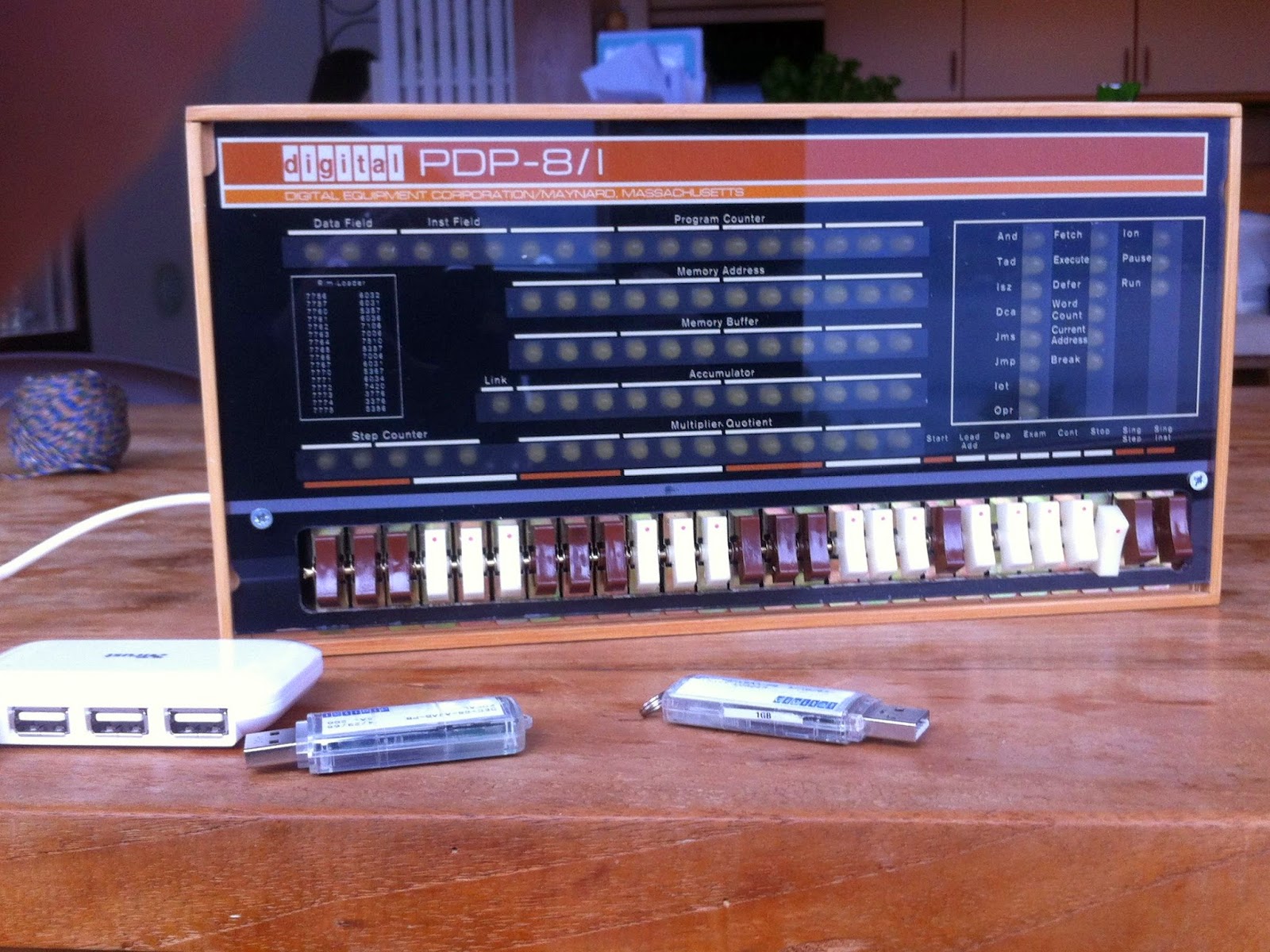
PiDP-8/I Simulator
I have a brief but ancient history with the PDP-8 from Digital Equipment Corporation. I started working for DEC in the winter of 1977/78, just after my senior year in high school. I was in college studying radio/television production. When a film crew arrived one day to make a training video for the company, I asked if I could intern on the project. I’d worked there a while by then and had a good relationship with my boss, so I got a green light to do it.
The training video project was for a dedicated bed-of-nails tester for the new PDP-11/23 board that was about to go from prototype assembly to full production in Puerto Rico. The facility that I worked at performed central incoming chip testing as well as the prototype assembly process for the PDP-11/23. All of the test equipment was driven by DEC PDP computers, which was pretty impressive.
The test machine we were making a video for had a massive amount of input/output pins that were controlled by the PDP-8. It had a paper tape reader, an RK08, a console terminal interface and an expansion chassis that led to the 3rd-party I/O pin controllers and timing hardware. The bed of nails fixture was built specifically for the PDP-11/23 and used sharp spring loaded pogo pins for connectivity to all the “special places” to be probed on the underside of the board.
In the training video, I showed how to perform the boot process, that involved loading a series of commands into the front panel in octal. These steps told the machine how to read the paper tape. The next step was to run what the paper tape loaded (The tape drive), which was the program that knew how to spin up and use the RK08 disk and make the serial terminal work. From there, the text application could be executed from the operator terminal.
So where is all this leading?
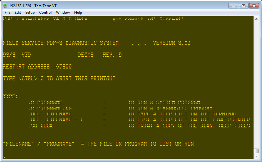
I just purchased a kit from Oskar Vermeulen called PiDP-8, a PDP-8/I simulation with real front panel switches and blinken lights. Yes, Blinken does mean “to flash” in German. The kit is based on a Raspberry Pi and uses the SIMH computer simulation program.
 PDP
PDPHis website is at Obsolescence Guaranteed
I’m still waiting for the kit to arrive… but I have the PI running.
Being creative in electronics as a hobbyist
I am not an Electronics Engineer. I am not officially trained and have no related certifications. I am however, what I would call “experienced”. I was introduced to electronics as a hobby in the late 1960’s as a kid in home where electronics was paying the bills, so to speak. My father was, at the time, an electronics systems technician working for a large military contractor.
It probably started the day I “went to work” with him and he showed me the project he was working on… It was a missile launch system loaded with cool control panels and of course, Nixie number indicator tubes.
So, at around age 13 or 14, I wanted to know how all this stuff worked. Unlike today, we had nothing like the Internet so find out how stuff worked involved going to the library and reading books or the magazines of day like Popular Electronics. My dad also had a collection of technical books and schematics that I would read over and over again.
So it started to become clear to me that a “designer” would use a collection of parts and arrange them in a particular way to take advantage of their physical “laws” to achieve a particular result. It also became clear that the characteristics of each individual part were as important as how they were assembled together. A particular device is chosen based on the effect it’s value and parameters have on the overall assembly. It sometimes became clear to me that some parts are chosen based on availability and commonality making them what the assembly is built around.
In my case, I started to understand schematics and the meaning of the symbols rather quickly. I also discovered that unless I truly know what a part does, I don’t try to design with it. This lead to the start of a collection of component “data books”. Logically, these are no longer produced as it requires dead trees and we are much better served by online PDF files known as “Data Sheets”.
So, what does it mean to be a hobbyist?
Well, we are actually able to willfully misuse parts in ways they were never intended to be used, which is a luxury a professional designer doesn’t have. We don’t have a boss looking over our shoulder saying “Is it done yet? We are on a schedule here!”. In short, we can play. We can be creative. We can build and not be driven by time constraints and production budgets. We can have fun.
Where to start?
1) Try to learn some electronics theory. Nothing too deep. You should not have to go far beyond learning OHMS Law to be good enough. Lot of web resources exist already
2) Sketch your ideas out on paper before starting on the breadboard.
3) A solder-less breadboard and some jumper wires
4) Datasheets are king. Don’t try to use a part, especially a transistor or integrated circuit without one
5) Get some tools. You can get a good “temperature controlled” solder station for as little as $14. Wire cutters, needle-nose pliers and solder-sucker are all also high on the list of “should have’s”. A cheap un-controlled “fire-stick” or a “gun” type soldering iron are unsuitable for electronics.
With that out of the way… what’s next?
Find what interests you. For example, even after 50 years, we still use discrete transistors. It is still a major building block in electronics. Learning how they work can be a fun adventure so I’ll tell you about how I learned about transistors. I found a book in the library about transistor “multi-vibrators” and not having a clue what a multi-vibrator was, I started reading it. It turns out, it’s a circuit family based on a design using at least 2 transistors with a feedback path where the state of one transistor affects the state of another. Such a nice place to start. I learned about R/C (resistor/capacitor) interaction and how it could create a time delay and how this R/C behavior could create an oscillator or a circuit that could extend a small pulse into a long one.
Thus began my long journey of learning something new nearly every day… and the start of a fun hobby.
LC Meter revisited
So I really liked this LC meter that Kerry Wong came up with… with the understanding that it was based on a plethora of comparator based ocillator LC meters on the web but I wanted both less and more.
I wanted less of the Frequency meter… I already have ways to measure frequency… and I wanted to eliminate the DPDT L/C switch.
Here is my version of the circuit:

You probably already knew this but… latching relays are neat
So, I’m hanging out in IRC and a guy wants to be able to use a latching relay (and hasn’t bought one yet) and wants to know how it can help his battery operated Arduino device switch contacts but not lose power to an engaged relay coil. “Simple”, I say, and then realize that I had intended on researching small current latching relays for my own project.
So here’s the circuit.
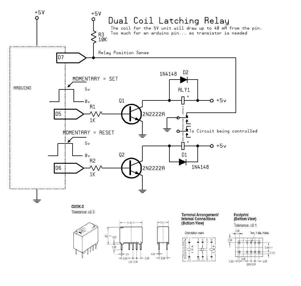
…and here’s the explanation.
The relay that was chosen is from the very likable OMRON G6 series of tiny relays. It is a dual coil type that latches to a position after a brief “impulse”. In this case… after the Arduino briefly supplies a connection to GND for the coil using an NPN transistor.
The specifics of the part are: G6SK-2-DC5 (You can check out the the full specs HERE )
This device is a 5V unit with a pair of 125 Ohm relay coils. (works out to be about 40 mA, too much for a MCU pin… so NPN drivers are required, not optional)
So, why do we have a DPDT unit? Because we need a spare pair of contacts to let the Arduino know which state the relay is in after power up… since it can be in either position when power off. The Arduino can know the relay’s current state by checking to see if (pin 7 in this case) a high is seen on the sense pin. The sense pin is set to draw 0.5 mA when in the SET state and 0 mA in the RESET state.
For the curious: Mouser.com stocks this part