No updates? I blame writers block…

Yeah, that’s the ticket.

So where am I as I start 2013.  Well, My Arduino based weather thingy is basically working.  The rain counter still dead… the now obsolete Maxim DS2423 seems a bad design choice now.  There must be a better way to keep track of the tipping rain bucket ( 5o tips per inch) that is non-volatile for those power outage times.

My Arduino based “make your own work bench tool” project is sort of stalled. Though I did find a neat oversize retro cabinet to put it in. (So 1980’s)

I’ll close up this update by sharing an old project… the Live For Speed Outgauge Bus Arduino interface (gear and RPM meter).

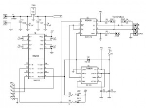
PC Network UDP to Serial conversion:  “PC CODE” and the Schematic.

Arduino Code: (pre-IDE 1.0)

 //----[ OutGaugeBus ]------------------------------------------------------
 // Name : OGBUS.PDE
 //-------------------------------------------------------------------------
 // Purpose : Receive serial commmands from "Live For Speed" INSIM OUTGAUGE
 // : Client and then display real-time dashboard information
 // : on Arduino based output devices, such as LED's.
 // : Live For Speed References:
 // : LFS/DOCS/INSIM.TXT
 // : http://en.lfsmanual.net/wiki/InSim_Tutorials
 // : http://www.brunsware.de/insim/
 // : See Also: http://www.lfs.net/
 //-------------------------------------------------------------------------
 // Date : 25 Oct, 2007 ( Started as a Parallax SX28 project )
 // Version : 2.11
 // Modified: 12/22/2010 11:30:34 AM
 // Author : Pete Willard
 // :
 //Additional:
 // Credits : * Mike McRoberts - Earthshine Design -
 // : Arduino Starter Kit PDF
 // :
 // : * Hacktronics - http://www.hacktronics.com/Tutorials
 // :
 // : * Arduino ShiftOut tutorial
 // :
 // : To keep code "recognizable", available references were used
 // : and changed very little from reference sources listed above.
 //-------------------------------------------------------------------------
 // Notes : Includes using a 74HC595 Shift Register for the Bar Graph
 // : and discrete 7-segment display for gear indicator
 // :
 // : Commands come from OGBUS.EXE (DevC++ UDP Client) and convert
 // : INSIM OUTGAUGE data into serial packet data for Arduino
 // : INSIM Client Software will send ALL vaalues every update
 // : but can send as little as Clear Command "C0"
 // :
 // : Expansion:
 // : With a little creative wiring, it would be possible to
 // : daisy chain multiple serial Arduino boards or if USB is
 // : used, multiple OGBUS clients can be run at one time
 // :
 // : Command Examples:
 // : (Comma Separated Values) Any Order up to 24 Characters
 // : Format: <command></command>,<command></command>...
 // : C0 = Clear All Outputs
 // : G0-G8 = Gear Indicator
 // : R0-R8 = RPM Bargraph
 // : S0|S1 = Shift Light Pin On|Off (binary)
 // : P0|P1 = Pit Limiter Pin On|Off (binary)
 // :
 //-------------------------------------------------------------------------

//----[ Variables ]--------------------------------------------------------
 const int buffsize = 25; // Buffer Size
 char buffer[buffsize]; // Incoming Serial Data Buffer
 int debug = 0; // Set to NON-ZERO to test with Serial Monitor
 int ledCount = 8; // The number of LEDs in the Bar Graph LED
 //-------------------------------------------------------------------------
 // Seven segment LED layout for the Gear Indicator
 // Arduino pins must be sequential
 int GIstartpin = 2;
 // Arduino pin: 2,3,4,5,6,7,8
 byte seven_seg_digits[9][7] = { { 0,0,0,0,1,0,1 }, // = R
 { 0,0,1,0,1,0,1 }, // = N
 { 0,1,1,0,0,0,0 }, // = 1
 { 1,1,0,1,1,0,1 }, // = 2
 { 1,1,1,1,0,0,1 }, // = 3
 { 0,1,1,0,0,1,1 }, // = 4
 { 1,0,1,1,0,1,1 }, // = 5
 { 1,0,1,1,1,1,1 }, // = 6
 { 0,0,0,0,0,0,0 }, // = 7 (blank)
 };
 // a b c d e f g ------> LED segment
 //-------------------------------------------------------------------------
 // Bargraph Values for 8 LED Bargraph
 // Only 8 values of BYTE are needed to light the 8 bargraph LED's
 // sequentially
 // NOTE: Most Bargraph LED's are "10 unit" so I have bottom 2 and top 2
 // LED's tied together.
 // Part Number used: AVAGO "HDSP-4832" 3-Green 4-Yellow 3-Red
 // Mouser Part Number: 630-HDSP-4832
 // The Shift Register lowest outputs start with Green Anodes of the
 // Bargraph.
 //
 byte bargraph[9] = {0x00,0x01,0x03,0x07,0x0F,0x1F,0x3F,0x7F,0xFF};
 //-------------------------------------------------------------------------
 // LED PINS - optional since we are low on pins
 int shiftlight = 12;
 //int pitlimit = 13; // Pick one
 //int lowfuel = 13;
 //-------------------------------------------------------------------------
 // 74HC595 Pin Setup
 int latchPin = 9; // Pin connected to ST_CP (12) of 74HC595
 int clockPin = 10; // Pin connected to SH_CP (11) of 74HC595
 int dataPin = 11; // Pin connected to DS (14) of 74HC595

//----[ SETUP ]-----------------------------------------------------------
 void setup() {
 // Speed needs to match INSIM - Outgauge Client Configuration setting
 Serial.begin(19200);
 Serial.flush();

// Set all pins to Outut Mode
 int a;
 for(a=0;a < 13;a++){ pinMode(a, OUTPUT); 
 } 
} 

//----[ MAIN LOOP ]------------------------------------------------------ 
void loop()  { 
// Mike McRoberts serial input command routines 
// from the "Serial Controlled Mood Lamp" example 
// in Arduino Starter Kit Manual from Earthshine Design 
if (Serial.available() > 0) {
 int index=0;
 delay(10); // let the buffer fill up
 int numChar = Serial.available();
 if (numChar>buffsize) {
 numChar=buffsize;
 }
 while (numChar--) {
 buffer[index++] = Serial.read();
 }
 splitString(buffer); // Process Serial Packet
 }
 }

//----[ SubRoutines ]----------------------------------------------------

void splitString(char* data) {
 // also from "Serial Controlled Mood Lamp" example

if (debug) {
 Serial.print("Data entered: ");
 Serial.println(data);
 }

// Sequentially De-Tokenize the Serial Commands received
 char* parameter;
 parameter = strtok (data, " ,");
 while (parameter != NULL) {
 // Pass result to parseCMD for each Command received
 parseCMD(parameter);
 // remove processed commands from the list
 parameter = strtok (NULL, " ,");
 }

// Clear the text and serial buffers
 for (int x=0; x<buffsize; x++) {
 buffer[x]='\0';
 }
 Serial.flush();
 }

//=======================================================================
 void parseCMD(char* data) {
 // Flexible, easily expanded Command Parser
 // based on "Serial Controlled Mood Lamp" example
 // *** Marvelous coding by Mike MCRoberts

//--[gear]---------------------------------------
 if ((data[0] == 'G') || (data[0] == 'g')) {
 // Have command, now get Argument "value" while removing whitespace
 int ArgVal = strtol(data+1, NULL, 10);
 // then limit the results to what we expect for this command
 ArgVal = constrain(ArgVal,0,8);
 sevenSegWrite(ArgVal);

if (debug) {
 Serial.print("Gear is set to: ");
 Serial.println(ArgVal);
 }
 }

//--[shift light]--------------------------------
 if ((data[0] == 'S') || (data[0] == 's')) {
 int ArgVal = strtol(data+1, NULL, 10);
 ArgVal = constrain(ArgVal,0,1);
 digitalWrite(shiftlight,ArgVal);

if (debug) {
 Serial.print("SHIFT is set to: ");
 Serial.println(ArgVal);
 }
 }

//--[reset]--------------------------------------
 if ((data[0] == 'C') || (data[0] == 'c')) {
 int ArgVal = strtol(data+1, NULL, 10);
 ArgVal = constrain(ArgVal,0,1);

sevenSegWrite(8);
 shiftWrite(0x00);

if (debug) {
 Serial.print("Clear Outputs");
 }
 }

//--[rpm bar graph]-----------------------------
 if ((data[0] == 'R') || (data[0] == 'r')) {
 int ArgVal = strtol(data+1, NULL, 10);
 ArgVal = constrain(ArgVal,0,8);

shiftWrite(bargraph[ArgVal]);

if (debug) {
 Serial.print("RPM is set to: ");
 Serial.println(ArgVal);
 }
 }

} // End parseCMD Loop

//=======================================================================
 void sevenSegWrite(byte digit) {
 byte pin = GIstartpin;
 for (byte segCount = 0; segCount < 7; ++segCount) {
 digitalWrite(pin, seven_seg_digits[digit][segCount]);
 ++pin;
 }
 }
 //=======================================================================
 void shiftWrite(byte Rdata){
 // prepare the register for data
 digitalWrite(latchPin, LOW);
 // shift out the bits:
 shiftOut(dataPin, clockPin, MSBFIRST, Rdata);
 //Set the latch pin high to enable the outputs
 digitalWrite(latchPin, HIGH);
 }
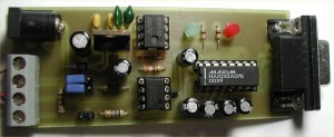
RS485 – The PC side

RS485 with Automatic Transmit Enable
Here is a simple RS232-485 converter for the PC serial port I developed with the help of a Circuit Cellar article by Jan Axelson about RS485 interfacing.
It uses a 555 as a monostable to enable the transmit mode only when “sending”.
It’s a pretty basic circuit and nothing special is really happening here other than the portion involving the LM555 timer. The termination jumpers allow the 120 OHM termination on the master node as well as the balancing termination resistors connected to +5V and GND.
There were only minor changes throughout development. For example, originally the indicator LED’s were ON unless sending since they were tied to GND. Now then go LIT when sending, which is more intuitive, I suppose.
Here is the circuit:

Overall this was an Easy Project.
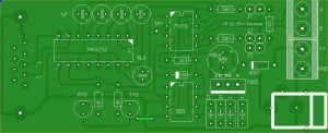
And yes, this is a HOMEBREW toner transfer method PC board. The DRAWING package is NOT EAGLE but rather ABACOM SPRINT LAYOUT and ABACOM SPLAN.

Tagged

Weather Shield

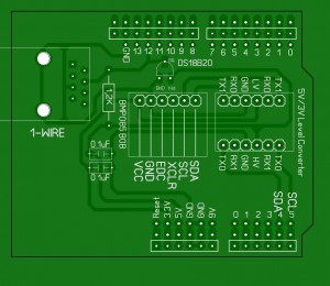
I grew tired of working with a solderless breadboard and was worrying about the wires falling out of the makeshift  INSIDE portion of the DALLAS 1-wire weather station circuit I am working on (also the interface to other assorted 1-wire stuff outside) so I decided it was time for a PCB. The board contains a 2-wire BMP085 pressure sensor BOB and level converter… as well as a 1-wire temperature sensor.  This board contains the 1-wire bus connection (RJ45) to the outside world.


Here is the design I came up with:

A reference to how heat can impact common components

I decided to pull some information from old notes while cleaning up the really old paper in my desk.  Here is a list I created to remember how heat (in excess of 100°F) can impact common parts like capacitors and transistors, etc.

Selector Switch with ARDUINO

A fellow Arduino guy from Texas asked about how to set up a multi-mode selector switch using a single pushbutton and 3 states (not including the boot up state). What follows is this discussion that we had becoming a back and forth collaboration of ideas until I got off work and decided to see if I could make it more robust and simpler at the same time.

Lets talk about the original code…  it essentially worked… with some quirks.

The original code would continuously set all the pins… every loop, even though it didn’t need to…

It also tried to process the loop even if the mode was equal to zero (IE; No button presses have occurred yet and in that case, all LED’s should be off)

Lastly, it got weird when mode was incremented to 4 and set back to 1 and in here is the behavior that I wanted to eliminate.  It would change to mode 1 and 2 and 3 when the key was PRESSED but would only go back to mode 1 when button was released when in mode 3.  This is just not the way to make all the button presses seem similar.  All the other buttons react on the button press, not the release.

So it was SWITCH/CASE to the rescue.  With switch case statements I could handle all the mode switching and deal with mode 1 and any other mode that was not 2 or 3 with the default statement.  This allowed it to have all button mode migration to appear to behave the same.

The code also makes sure that pins do not get changed when they don’t need to be… IE; every loop traversal.

On to the final code example…

/*
 Using a single switch to select between 3 modes
*/
// Schematic: http://www.pwillard.com/files/mode4.jpg
//===============================================================
// Global Variables & Constants
//===============================================================

const int ledPinOne = 2; // LED1 ANODE
const int ledPinTwo = 4; // LED2 ANODE
const int ledPinThree = 7; // LED3 ANODE
const int modePin = 13; // Active HIGH, held low by 4.7K

int mode = 0; // Selector State (Initial state = ALL OFF)
int val = 0; // Pin 13 HIGH/LOW Status
int butState = 0; // Last Button State
int modeState = 0; // Last Mode State
boolean debug = 1; // 1 = Print Serial Enabled / 0 = disabled

//===============================================================
// SETUP
//===============================================================
void setup () {
 pinMode(ledPinOne, OUTPUT);
 pinMode(ledPinTwo, OUTPUT);
 pinMode(ledPinThree, OUTPUT);
 pinMode(modePin, INPUT);
 if (debug){
 Serial.begin(9600);
 Serial.print("Initial Mode: ");
 Serial.println(mode);
 Serial.print("Setup Complete\n");
 }
}

//===============================================================
// Main Loop
//===============================================================
void loop() {

 val = digitalRead(modePin);

 // If we see a change in button state, increment mode value
 if (val != butState && val == HIGH){
 mode++;
 }

 butState = val; // Keep track of most recent button state

 // No need to keep setting pins *every* loop
 if (modeState != mode){

 // If no keys have been pressed yet don't execute
 // the switch code below
 // if (mode != 0) {

 switch ( mode ) {
 //case 1 is actually handled below as default

case 2:
 digitalWrite(ledPinOne, LOW);
 digitalWrite(ledPinTwo, HIGH);
 showState();
 break;
 case 3:
 digitalWrite(ledPinTwo, LOW);
 digitalWrite(ledPinThree, HIGH);
 showState();
 break;
 default:
 mode = 1;
 // loop back to 1 by default, seems redundant but
 // it also handles the "mode is > 3" problem
 digitalWrite(ledPinThree, LOW);
 digitalWrite(ledPinOne, HIGH);
 showState();
 break;
 } // end switch
// } // end of "if mode = 0" check
 } // end of ModeState check
 modeState = mode; // Keep track of mode recent mode value
 delay(10); // slow the loop just a bit for debounce
}

//===============================================================
// Subroutine
//===============================================================
void showState() {
 if (debug){
 Serial.print("Mode: ");
 Serial.println(mode);
 }
}

Tagged

Current Weather Station

Arduino Mega

AAG One Wire Weather Instrument Series 2. (Wind Speed, Temperature, Wind Direction)  DS18B20 temperature, DS2423 (wind speed) DS2450(wind vector)

Hobby Boards: Humidity/Temperature Board – Built from my own parts

Rain Gauge (See my post about it)

BMP085 – Pressure Sensor

Internal Temperature via DS18B20

1-Wire Power Injector (see my “how to make a PCB guide):

In progress: COSM upload – nope.

FAIL:  Adding COSM/PACHUBE support ran me out of working RAM… so project for upload of data is scrapped at the moment.

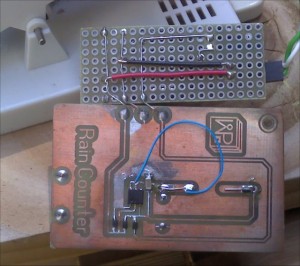
Updated Rain Gauge

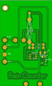
Newest Rain Counter

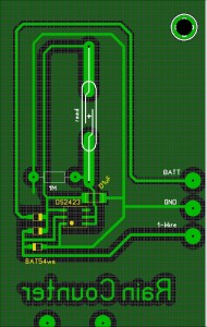
So I’m taking the time to re-do the rain gauge. The existing one clearly had some issues (hacks/fixes) and I wanted to also gain the use of counter B (if possible) for a different piece of weather gear.

Rain Counter version 7

I was also able to get a hold of some “liquid tin” from MG Chemicals to see if it compares well to Cool-AMP powder as a copper plating solution.

Results:

While the Liquid Tin is much easier to apply, I actually don’t like it as much as the Cool-Amp coating.

Weather Station – Hacked Rain Gauge

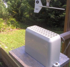
Converting a broken  LaCrosse WS-9004U 915MHz WIRELESS RAIN GAUGE into a “wired” 1-wire  0.02 inches per tip rain gauge.

The Lacrosse unit is an inexpensive rain gauge available from my local Fry’s store for about $24.  They are unusually finicky when being set up so I already knew I didn’t really have a lot of love for the device.  After about 6 months, my unit stopped sending/receiving updates and no amount of new batteries, resets or pairing attempts seemed to help.  I tossed it into my junkbox of parts.

Right around the time that MAXIM decided that making 1-wire devices was “tooo haaarrd”, (said in a whiner voice) and they killed off the DS2423 counter device, I decided to buy some before they were totally gone to see if I could make my junkbox tipping bucket hardware work in a “wired” mode.

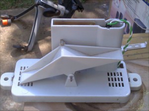
It wasn’t really that hard.  I used a sample design from my WEATHERTOYS book, (AUTHOR: Tim Bitson), and  after ripping all the guts out of the device (wireless sender and battery holder, I had some room for some 1-wire related parts.

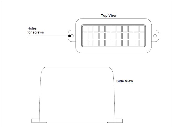
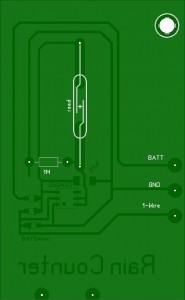
The original PCB  fits in a nice slot in the plastic case and used a reed switch aligned with a magnet attached to the center of the tipping bucket.  I used the dimensions to create a replacement board and everything fit except the CR2032 battery needed by the counter to not lose data when 1-wire was shorted or disconnected.

Original Board:

The CR2032 nicely fit into the area where the prior AAA batteries were housed.

The 1-wire connection is made by using a weatherproof gel-filled crimp splice available from the local hardware store.

The code (java in my case) is straight from the Weathertoys book with adjustments made relating to the side of the tip, 0.02 inches per tip.

Installation

The Guts

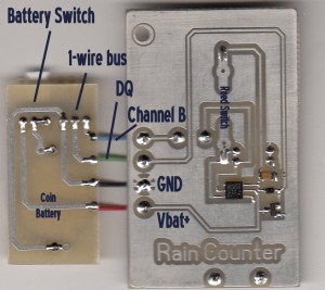
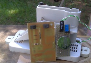
The main board and battery board

The backside

Note: Not my best work…  I attempted to re-orient the reed switch during testing, which only managed to a) break a reed switch and b) break a copper trace (fixed with blue wire).  In addition, I actually installed the wrong SMD part that I thought was a DS2423… which turned out not to be the case…

I suppose I could make a new board… but once this one started working… I just left it alone.

The gauge is currently off the station since I forgot to paint the plank, made from ash, used to mount the sensor.  Small ants were using the aging cellulose to create a fungus garden under the cover of the rain collector.  Silly me.  Now I must replace and paint the replacement wooden board.

Next Step.  Stop using a Linux server and JAVA and convert over to an Arduino  MEGA2560 as a weather station controller.

Weather Station Woes

I might have mentioned that my AAG WS603B Weather Station turned out to be the most oddball replacement for my original 1990’s Dallas 1-wire Weather instrument.  It worked reliably for 10 years.  I had version 1.0, which was rather difficult to program for as it used the DS2401 serial number for each wind direction.  This required a lot of extra  1-wire coding.

I’ll spare you some of  the gory details regarding the quality of the latest AAG unit though I should mention that it was incompatible with all 1-wire wiring standards to date.

The real problem with the new unit (other than reliability) was that the new case is clear (no so bad) full of colored LED’s (can you say SILLY?) and not water resistant. Even though the case seemed closed and the PC board was “sealed”, it still managed to die after 6 months of usage.   It took 6 months of trying to get the Windows software from them for the station… by then… the device was dead. I’ll not be buying anything else from AAG.

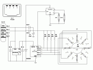
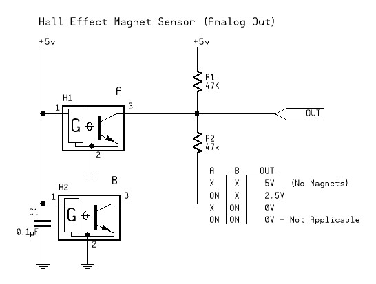
Anyway, one of the design ideas that AAG implemented was actually quite sensible. They used HALL sensors for Wind Direction instead of the fragile reed switches as used with other station designs. The Dallas Version 2 weather station (formerly sold by AAG) used a DS2450 and reed switches to track 16 positions of wind direction with just 1 magnet rotating. Only 8 sensors were needed as the intermediate positions were resolved when the magnet straddled two sensors at once.

Dallas Weatherstation version 2 Schematic:

I attempted to recreate this solution with Hall Effect Sensors. My first test circuit is below. Seems to work well.

So now my plan is to rebuild a replacement for the failed board in the WS603 housing.

Creating a weather station with Linux

Long ago I decided that I wanted to keep track of local weather. This is somewhat related to my desire to keep an eye on my raised bed gardens during the summer and partially due to my desire to have fun electronics projects to keep me doing “fun things”. I had already started with 1-wire and had a few devices that I either purchased or made myself.

As a first pass, I decided to see if I could get all my sensors working under Linux before attempting the Arduino weather station  conversion.  That said, It would have been easier if I had decided to use Windows and follow Tim Bitson’s examples from his “Weather Toys” book. The book provides guidance for MacOS and Windows only. That’s really not a show stopper though as I was able to get everything working.

Step 1: Install Linux

Install Ubuntu Linux workstation version 9.10 LTS (I tried newer versions but they have some annoying issues)

Step 2: Installing JavaVM and RXTX

Note: A version of Java is installed by default, It’s just not the one I want.

I installed the full suite of latest SUN JAVA (not default OPENJDK and note that the SUN install requires enabling partner repositories – Google for instructions about enabling and then the JAVA install is simple)

Install RXTX with the command

sudo apt-get install librxtx-java

(It does all the tricky bits for you)

Step 3: OneWire support for JAVA

Download OneWireAPI “http://files.dalsemi.com/auto_id/public/owapi_1_10.zip
Extract contents  to a convenient location and get setup to copy files.
Copy the file OneWireAPI.jar to /usr/share/java/OneWireAPI.jar

The Java Libraries get installed to /usr/share/java. This is default behavior for librxtx-java install, so I used the same solution for OnewireAPI (manually copied)

Step 4: NETBEANS

In my case, this is version 6.8, installed from Synaptic Installer or you could use:

sudo apt-get install netbeans

Netbeans will create a project directory by default in your home folder. Your code goes here.

Libraries:
When defining the library settings for NETBEANS, it’s as simple as the two entries in the “libraries” section, as shown in the book.
a) /usr/share/java/OneWireAPI.jar
b) /usr/share/java/RXTXcomm.jar

Step 5: Grab WEATHERTOYS code.

Here

General Notes

I use the AAG TAI603B interface (USB-SERIAL & 1 Wire Power Injector with home made Hobby Boards adapter) and this is automatically recognized as a device by this version of Linux. In my case, it is a serial device, coded as:

public static final String ONE_WIRE_SERIAL_PORT = "/dev/ttyUSB0";

and seen by the API as:

public static final String ADAPTER_TYPE = "DS9097U";

You can find the ports available with the following command:

sudo dmesg | grep tty

You will likely see something like:

"/dev/ttys0" or  "/dev/ttyUSB0"