… and these things are really neat.
Ok, so what is a Spark Core? Wait… lets start with the fact that this was a Kickstarter project that succeeded and is now a full fledged product that sadly I did not know about until afterwards. I’d have been there supporting this Kickstarter if I had known about it. I tried to support a different but *very* similar Kickstarter project (well, not tried, I did support it) and have yet to see the product that is now many many months late. Now that I have the Spark core, and I like it, I’m pretty sure I won’t care when the Flutter *finally* arrives.
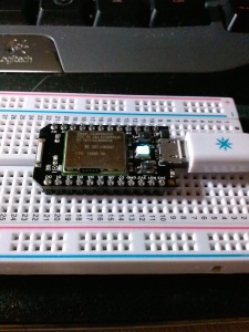
spark core
So, back to what a Spark Core is. It is a small device, roughly the size of an oversize collector edition US postage stamp. It’s designed to fit into a Solder-less breadboard for easy project development and comes in 2 flavors… one with an on-board “chip” antenna and one with a small antenna jack that allows you to install your own wifi antenna… I grabbed an antenna out of my pile of broken wifi routers. I wasn’t sure it would work… but seems to work just fine and uses the same RF jack (imagine that?).
For more information on what a Spark Core is, go here: Spark Core Getting Started
So what am I doing with it? Well, I’m learning what it can do first… and that’s a tiny bit tricky. The documentation is written more geek than noob friendly and while I have no issue with the documentation in general, it does seem to have some gaps here and there. I suppose with time this will all get better.
For example; they did make it seem like it would do some automagic things to get it quickly “registered” in the cloud and that my phone app could talk to it right away. No such luck. My Phone app never found the device and the status LED said I was happily connected. I needed to go through a rather manual process of attaching to the device in a serial debug mode to capture my unique ID to claim my core manually. Again, it was supposed to just work… but a quick check says I’m not the only one this happened to. (ed. I did acquire an additional spark core and the second one installed and connected and was claimed without a hiccup)
With that initial stumble out of the way… I needed to see how Arduino compatible this is so I started writing some code. As long as I stick to true Arduino’s abstract language (and not hardware dependent short cuts like you might find in some existing libraries) all is well. This device does not have an AVR MCU at it’s heart. It uses an STM32 MCU which is a much more capable device coupled with a TI CC3300 wifi in-a-box chip to create a complete arduino-like wifi device in a seriously small package.
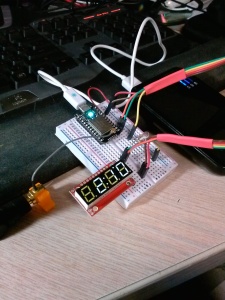
My first project on the device after playing with examples is a simple “always correct” LED clock using the SparkFun 4 digit seven segment serial LED. It works… and displays the correct time as soon as it boots up with no need for battery backup or an RTC chip. The part number COM-11629. This is a mildly depressing LED display due to the fact that it is running on 3.3 volts and has 1000 Ohm current limiting resistors on the LED’s. (Did I mention that the Spark Core is a 3.3V device? No? oops.)
Seriously… 1000 Ohms at 3.3 volts is not the ideal value of the current limiting resistors. It should be around 47 Ohms… not 1000 Ohms. The end result is you can only really see the display in the dark.
Anyway… the code part works… It uses built in features like wire library and time library that are already in the API. Here, see for yourself*…
//==============================================================================
//  III  2222   CCCC  CCCC L     OOOOO  CCCC K   K
//   I       2 C     C     L     O   O C     K  K
//   I    222  C     C     L     O   O C     KK
//   I   2     C     C     L     O   O C     K K
//  III  22222  CCCC  CCCC LLLLL OOOOO  CCCC K   K
//==============================================================================

//==============================================================================
// Program:      I2Cclock
// Author:       Pete Willard
// Version:      1.0
// Target:       SparkCore
// Date:         2014/12/04
// Time:         08:14:45
// Notes:

// This program is free software: you can redistribute it and/or modify
// it under the terms of the GNU General Public License as published by
// the Free Software Foundation, either version 3 of the License, or
// (at your option) any later version.

// This program is distributed in the hope that it will be useful,
// but WITHOUT ANY WARRANTY; without even the implied warranty of
// MERCHANTABILITY or FITNESS FOR A PARTICULAR PURPOSE.  See the
// GNU General Public License for more details.

// You should have received a copy of the GNU General Public License
// along with this program.  If not, see <http://www.gnu.org/licenses/>.

//
// Reference:
//  Used rather sketchy Sparkfun serial LED display "datasheet"
//  Part #  COM-11629 - Note: it's a rather dim display.
//==============================================================================
 # define bitSet(value, bit)((value) |= (1UL << (bit)))
 # define bitClear(value, bit)((value) &= ~(1UL << (bit)))

//=====[ CONSTANTS ]============================================================
// # define DEBUG 0 // 0 = debugging disabled, 1 = enabled
//This is the default address of the OpenSegment with both solder jumpers open
 # define DISPLAY_ADDRESS1 0x71

// definitions from sparkfun for bitwise led controls (decimal/colon/dot)
 # define COLON 4
 # define DOT 5

// Time Sync and Time Zone settings
const int syncInterval = 60 * 60 * 8; //sync every  4 hours

static signed char const DEFAULT_TIME_ZONE = -4;

//=====[ VARIABLES ]============================================================
long millisTimer;
int lastSync = 0;
boolean colonOn = false;
boolean ampm = true;
char bits; // used to track binary values for bitwise

//=====[ SETUP ]================================================================
void setup() {


	Spark.connect();
	 while(Spark.connected() == false) {
	     delay(100);
	 } while(Time.year() == 1970)
	  {
	     Spark.syncTime();
	     Spark.process();
	     delay(100);
	  }
	 Spark.disconnect();
	 while (Spark.connected() == true) {
	     delay(100);
	     Time.zone(DEFAULT_TIME_ZONE);
	 }

	Wire.begin(); // join i2c bus as master
	Wire.beginTransmission(DISPLAY_ADDRESS1); // transmit to slave device #4
	Wire.write('v');
	Wire.write(0x7A); // Brightness control command
	Wire.write(100); // Set brightness level: 0% to 100%
	Wire.endTransmission(); // stop transmitting

}

//=====[ MAIN PROCESS LOOP ]====================================================
void loop() {
	ampm = Time.isAM();
	showTime();
	delay(1000);
	adjustTime();
}

//==============================================================================
void adjustTime() {
	if (lastSync + syncInterval < Time.now()) {
		Spark.syncTime();
		lastSync = Time.now();
	}
}

//==============================================================================


//==============================================================================
//  Must be called after a "begin.transmission()" command.
//==============================================================================
void colonFlash() {
	//Blink the colon every other second

	if (colonOn == true) {
		colonOn = false;
		bitClear(bits, COLON);

	} else {
		colonOn = true;
		bitSet(bits, COLON);

	}
	Wire.write(0x77); // control command
	Wire.write(bits); // Turns on colon
}

//==============================================================================
//  Must be called after a "begin.transmission()" command.
//==============================================================================
void setPM() {
	if (ampm == true) {
		bitClear(bits, DOT);
	} else {
		bitSet(bits, DOT);
	}

	Wire.write(0x77); // control command
	Wire.write(bits); // Turns on colon

}

//==============================================================================
void showTime() {
	char out[] = {
		0,
		0,
		0,
		0
	}; // place holder for time array

	char hour = Time.hourFormat12();
	char min = Time.minute();

	sprintf(out, "%2d%02d", hour, min); // format current time into char array
	Wire.beginTransmission(DISPLAY_ADDRESS1); // begin I2C transmit to device

	setPM();
	colonFlash();

	for (byte x = 0; x < 4; x++)
		Wire.write(out[x]); //Send a character from the array out over I2C
	Wire.endTransmission(); //Stop I2C transmission

}